b. Meters
1. Ammeter (A)
The ammeter (see Figure
2. Total Time Meter (TT)
The total time meter (see Figure
c. Manual Switches
1.Intake Heater Switch (HS) (see Figure
The intake heater switch is of the momentary type. When held in the PREHEAT position, the switch allows approximately 42 amps of battery current to flow into the intake heater, which preheats the air within the intake manifold and allows the engine to start. After starting the engine, the intake heater switch should continue to be held in the ON position for approximately 5 seconds until the engine has developed enough oil pressure to close the oil pressure safety switch.
2. Ignition Switch (IGN) (see Figure
The ignition switch is of the momentary type to be used in the OFF/ON/START positions. When held in the START (ignition) position, it energizes the starter motor solenoid, which in turn allows the starter motor to crank the engine. The switch is released to the RUN position once the engine has started.
3. Ignition Switch (IGN)(Auto Restart) (see Figure
The ignition switch is of the maintained contact type to be used in the RUN/OFF positions. When switched to the RUN position, it energizes the control module, which in turn controls all functions of the genset.
1.8 SAFETY DEVICES
Safety devices, such as circuit breakers, fuses, and safety switches, protect system components from damage.
The AC generator, solid state battery charger, fuel heater, high water temperature, safety relay, total time meter and intake air heater are protected by circuit breakers. If a safety device opens and there is an interruption of electrical current, the electronic governor module will be
In units with auto restart, the engine, engine control devices, and engine monitoring devices are protected by the auto restart module, low coolant sensor (if equipped), circuit breaker, low oil pressure switch, and high water temperature switch. These safety devices monitor system operating conditions and open a set of electrical contacts when an unsafe condition occurs. If a safety device opens and there is an interruption of electrical current, the electronic governor module will be
CONTROL |
| CONTROL | |
PANEL |
| BOX | 12 |
|
|
| |
2 | 3 |
| 13 |
|
|
| |
|
|
| 11 |
1 | 4 |
|
|
| 5 |
| 10 |
|
|
| |
| 6 |
|
|
| 7 |
| 9 |
|
|
| |
|
|
| 8 |
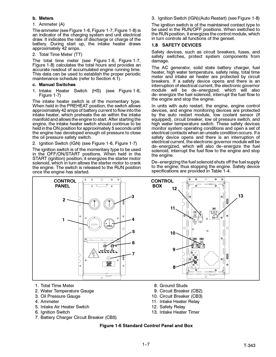
1. | Total Time Meter | 8. | Ground Studs |
2. | Water Temperature Gauge | 9. | Circuit Breaker (CB2) |
3. | Oil Pressure Gauge | 10. | Circuit Breaker (CB3) |
4. | Ammeter | 11. | Intake Heater Relay |
5. | Intake Air Heater Switch | 12. | Safety Relay |
6. | Ignition Switch | 13. | Intake Heater Timer |
7. | Battery Charger Circuit Breaker (CB5) |
|
|
Figure 1-6 Standard Control Panel and Box
|