4.4.10 Lube Oil Filter
The primary oil filter is located near the radiator fan (see Figure
1.After warming up the engine, stop engine, remove drain plug from oil reservoir and drain engine lube oil.
2.Replace filters. Lightly oil gasket on filter before installing.
3.Add lube oil (Refer to paragraph 1.10.f).
4.Warm up engine and check for leaks.
4.4.11 Engine Speed
The engine speed is electronically controlled. DO NOT
ATTEMPT TO ADJUST ENGINE SPEED.
4.4.12Replacing the Engine Speed Sensor 1. Disconnect the plug to the sensor.
2. Remove the bolt securing the sensor to the housing.
3. Remove the sensor from the housing.
4.Clean the recess in the housing to ensure that the sensor seats properly when
5.
4.4.13 Engine Air Cleaner
a. Inspection
The dry element or oil bath air cleaner should be inspected regularly for leaks. A damaged air cleaner or hose can seriously affect the performance and life of the engine. The air cleaner is designed to effectively remove contaminants from the air stream entering the engine. An excessive accumulation of these contaminants in the air cleaner will impair its operation. Therefore, a service schedule must be set up and followed.
1.Check all connections for mechanical tightness. Be sure the air cleaner outlet pipe is not fractured.
2.In case of leakage and if adjustment does not correct the trouble, replace necessary parts or gaskets. Swollen or distorted gaskets must always be replaced.
b. Air Filter Indicator
The air filter indicator is mounted on the unit frame and connected to the engine air intake. Its function is to indicate when the air cleaner element requires replacing. In operation: When a plugged air cleaner decreases intake manifold pressure to 500 mm (20”) WG, the indicator moves to the red line. The air cleaner element should be replaced and the indicator reset by pressing the reset button.
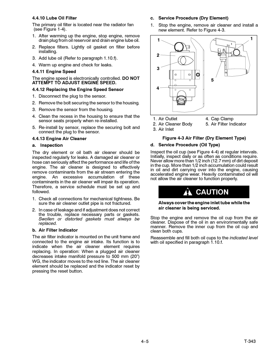
c. Service Procedure (Dry Element)
1.Stop the engine, remove air cleaner and install a new element. Refer to Figure
| 1 |
| 1 |
|
|
| |
| 2 |
|
|
| 3 |
|
|
|
|
| 5 |
4 |
|
| |
1. | Air Outlet | 4. | Cap Clamp |
2. | Air Cleaner Body | 5. | Air Filter Indicator |
3. | Air Inlet |
|
|
Figure 4-3 Air Filter (Dry Element Type)
d. Service Procedure (Oil Type)
Inspect the oil cup (see Figure
![]() CAUTION
CAUTION
Always cover the engine inlet tube while the air cleaner is being serviced.
Stop the engine and remove the oil cup from the air cleaner. Dispose of the oil in an environmentally safe manner. Remove the inner cup from the oil cup and clean both cups.
Reassemble and fill both oil cups to the indicated level with oil specified in paragraph 1.10.f.
|