SECTION 4
SERVICE AND PREVENTIVE MAINTENANCE
4.1 INTRODUCTION
This section covers service for the generator set and general engine service. Refer to the Kubota engine workshop manual, Section 1.1, for other engine servicing.
![]() WARNING
WARNING
Beware of moving
components.
4.2 PREVENTATIVE MAINTENANCE SCHEDULE
A tabular listing of the recommended preventative maintenance activities and schedule is provided in Table
4.3 BATTERY SERVICE
When replacing the battery, determine whether the unit was supplied with a mat in the battery tray. If so equipped, the mat must also be replaced.
4.4 ENGINE SERVICE AND COMPONENTS 4.4.1 Bleeding the Fuel System
The unit is equipped with a mechanical fuel lift pump, mounted on the engine next to the injection pump. The fuel system is a closed circuit, which will require bleeding if loss of fuel has occurred. To fill and bleed the system, do the following:
1.Turn fuel bleed valve (Red, see Figure
2.Turn the top of the manual priming pump (see Figure
3.Depress and turn the top of the manual priming pump clockwise to lock in place.
4.Start engine. (Refer to section 2.3).
5.When engine is running properly, turn fuel bleed valve clockwise until fully closed.
4.4.2 Servicing Fuel Pump Internal Filter
The internal fuel filter may become plugged or restricted with foreign particles or wax, which can develop if the wrong grade of fuel is used or untreated fuel is used in cold weather, contaminating the fuel. If the internal filter is plugged, the engine will lose power. Therefore, the filter must be cleaned on a regular basis. The quality of the fuel will affect the filter cleaning schedule (refer to section 4.2).
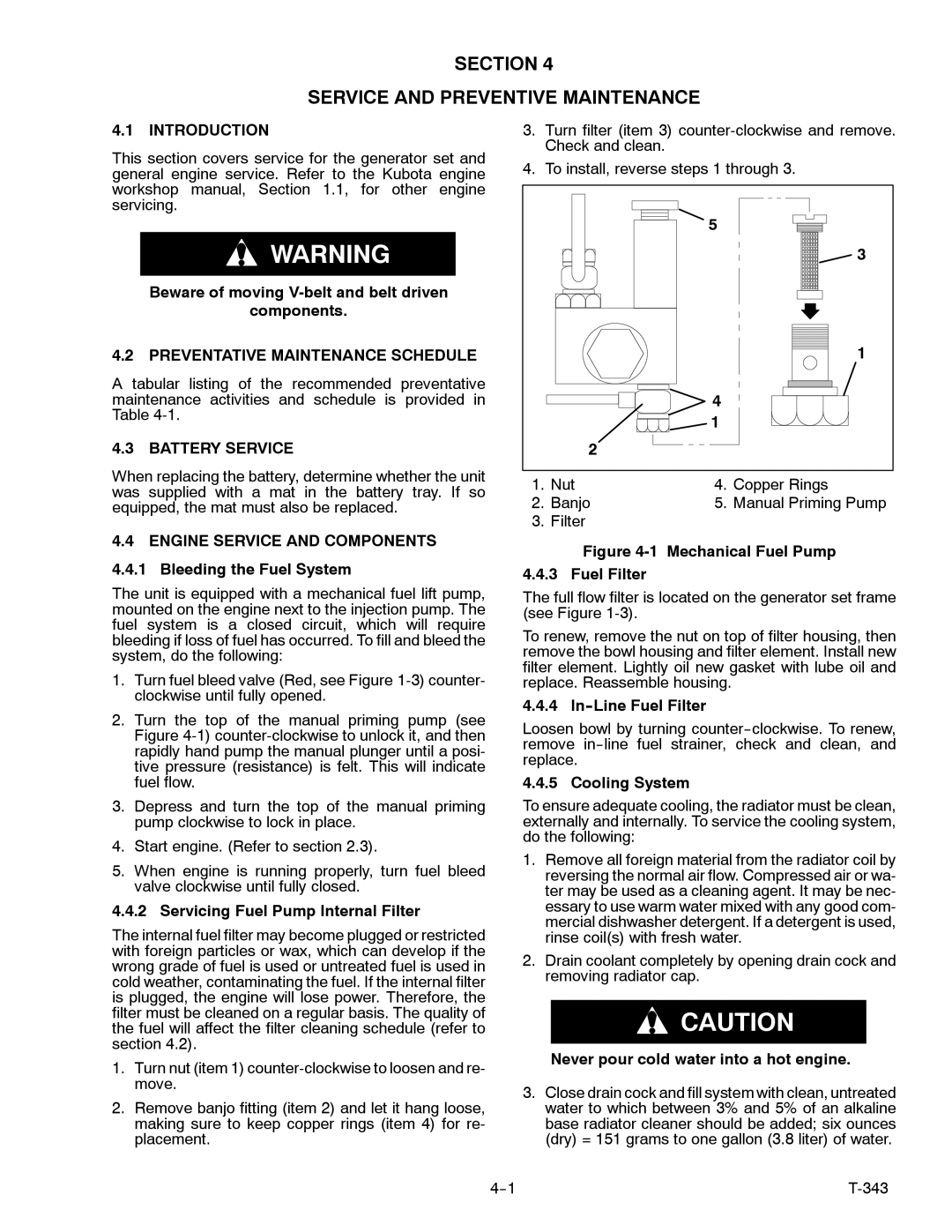
1.Turn nut (item 1)
2.Remove banjo fitting (item 2) and let it hang loose, making sure to keep copper rings (item 4) for re- placement.
3.Turn filter (item 3)
4.To install, reverse steps 1 through 3.
|
| 5 |
|
| 3 |
|
| 1 |
|
| 4 |
|
| 1 |
| 2 |
|
1. | Nut | 4. Copper Rings |
2. | Banjo | 5. Manual Priming Pump |
3. Filter
Figure 4-1 Mechanical Fuel Pump 4.4.3 Fuel Filter
The full flow filter is located on the generator set frame (see Figure
To renew, remove the nut on top of filter housing, then remove the bowl housing and filter element. Install new filter element. Lightly oil new gasket with lube oil and replace. Reassemble housing.
4.4.4 In--Line Fuel Filter
Loosen bowl by turning
4.4.5 Cooling System
To ensure adequate cooling, the radiator must be clean, externally and internally. To service the cooling system, do the following:
1.Remove all foreign material from the radiator coil by reversing the normal air flow. Compressed air or wa- ter may be used as a cleaning agent. It may be nec- essary to use warm water mixed with any good com- mercial dishwasher detergent. If a detergent is used, rinse coil(s) with fresh water.
2.Drain coolant completely by opening drain cock and removing radiator cap.
![]() CAUTION
CAUTION
Never pour cold water into a hot engine.
3.Close drain cock and fill system with clean, untreated water to which between 3% and 5% of an alkaline base radiator cleaner should be added; six ounces (dry) = 151 grams to one gallon (3.8 liter) of water.
|