Step 9 — Wire Field Controls
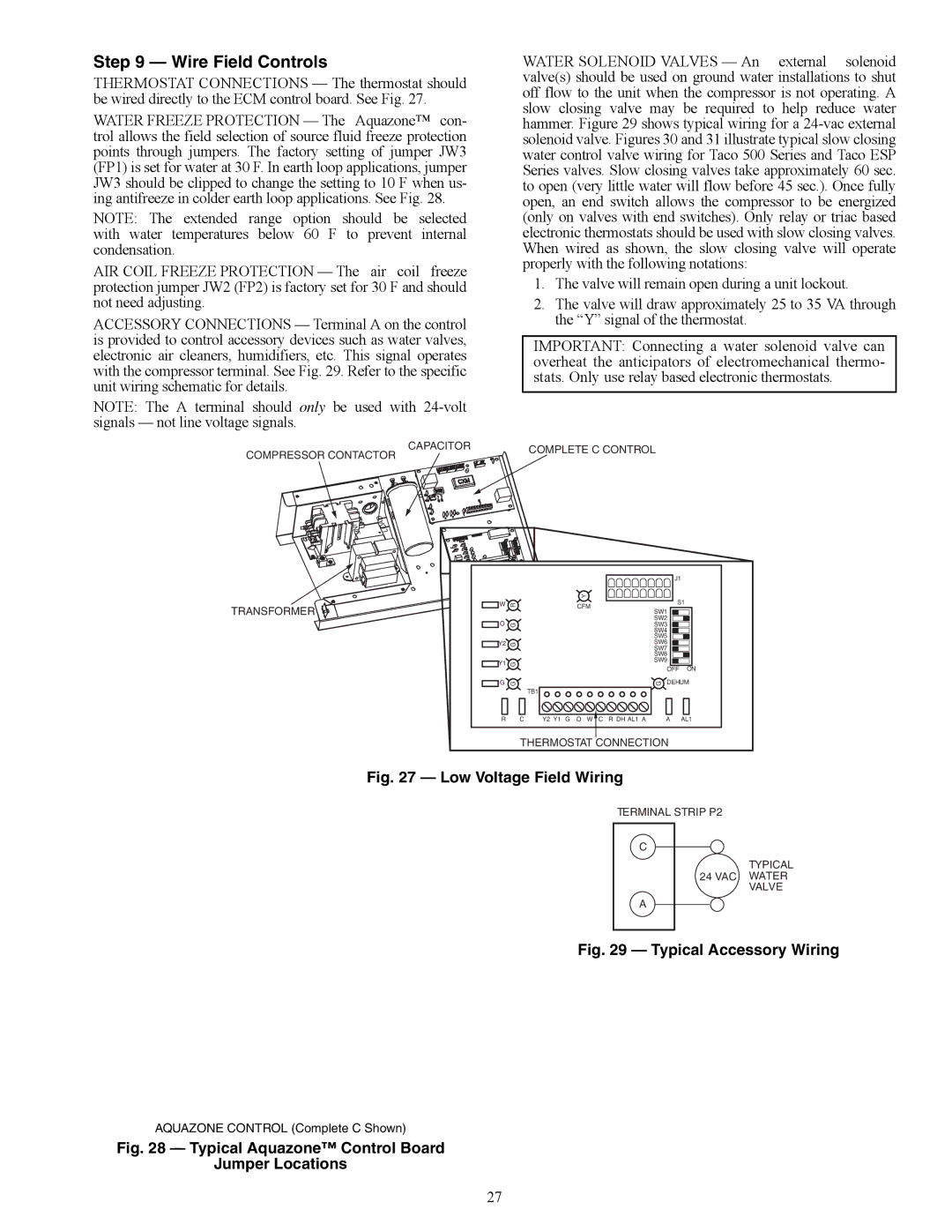
THERMOSTAT CONNECTIONS — The thermostat should be wired directly to the ECM control board. See Fig. 27.
WATER FREEZE PROTECTION — The Aquazone™ con- trol allows the field selection of source fluid freeze protection points through jumpers. The factory setting of jumper JW3 (FP1) is set for water at 30 F. In earth loop applications, jumper JW3 should be clipped to change the setting to 10 F when us- ing antifreeze in colder earth loop applications. See Fig. 28.
NOTE: The extended range option should be selected with water temperatures below 60 F to prevent internal condensation.
AIR COIL FREEZE PROTECTION — The air coil freeze protection jumper JW2 (FP2) is factory set for 30 F and should not need adjusting.
ACCESSORY CONNECTIONS — Terminal A on the control is provided to control accessory devices such as water valves, electronic air cleaners, humidifiers, etc. This signal operates with the compressor terminal. See Fig. 29. Refer to the specific unit wiring schematic for details.
NOTE: The A terminal should only be used with
WATER SOLENOID VALVES — An external solenoid valve(s) should be used on ground water installations to shut off flow to the unit when the compressor is not operating. A slow closing valve may be required to help reduce water hammer. Figure 29 shows typical wiring for a
1.The valve will remain open during a unit lockout.
2.The valve will draw approximately 25 to 35 VA through the “Y” signal of the thermostat.
IMPORTANT: Connecting a water solenoid valve can overheat the anticipators of electromechanical thermo- stats. Only use relay based electronic thermostats.
COMPRESSOR CONTACTOR | CAPACITOR | COMPLETE C CONTROL |
| ||
|
|
LINE | LOAD |
|
TRANSFORMER
a50-8197
|
| J1 |
|
| Y |
W | R | S1 |
CFM | ||
|
| SW1 |
O |
| SW2 |
G | SW3 | |
|
| SW4 |
|
| SW5 |
Y2 | G | SW6 |
| |
SW7 |
| |||
|
|
| ||
|
| SW8 |
| |
Y1 | G | SW9 |
| |
OFF | ON | |||
|
|
G | G |
|
|
|
|
| G | DEHUM | |
|
| TB1 |
|
|
|
|
|
|
|
R | C | Y2 Y1 G | O | W | C | R DH AL1 A |
| A | AL1 |
THERMOSTAT CONNECTION
Fig. 27 — Low Voltage Field Wiring
TERMINAL STRIP P2
C
A
TYPICAL
24 VAC WATER VALVE
Fig. 29 — Typical Accessory Wiring
AQUAZONE CONTROL (Complete C Shown)
Fig. 28 — Typical Aquazone™ Control Board
Jumper Locations
27