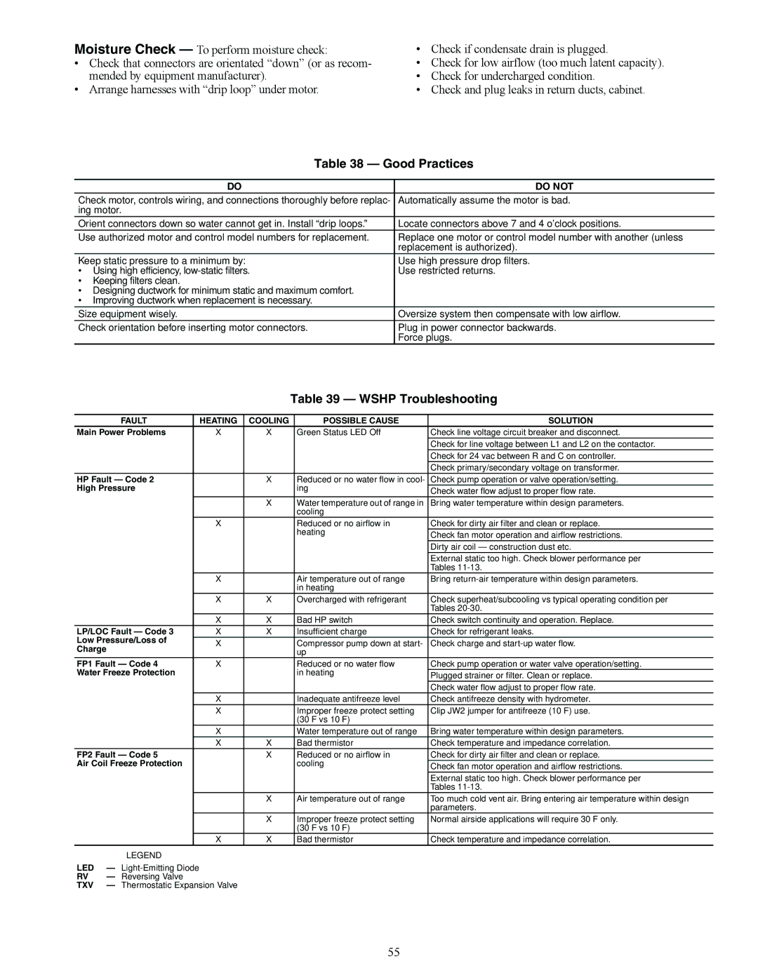
Moisture Check — To perform moisture check:
•Check that connectors are orientated “down” (or as recom- mended by equipment manufacturer).
•Arrange harnesses with “drip loop” under motor.
•Check if condensate drain is plugged.
•Check for low airflow (too much latent capacity).
•Check for undercharged condition.
•Check and plug leaks in return ducts, cabinet.
Table 38 — Good Practices
DO | DO NOT |
Check motor, controls wiring, and connections thoroughly before replac- | Automatically assume the motor is bad. |
ing motor. |
|
Orient connectors down so water cannot get in. Install “drip loops.” | Locate connectors above 7 and 4 o’clock positions. |
Use authorized motor and control model numbers for replacement. | Replace one motor or control model number with another (unless |
| replacement is authorized). |
Keep static pressure to a minimum by: | Use high pressure drop filters. |
• Using high efficiency, | Use restricted returns. |
• Keeping filters clean. |
|
• Designing ductwork for minimum static and maximum comfort. |
|
• Improving ductwork when replacement is necessary. |
|
Size equipment wisely. | Oversize system then compensate with low airflow. |
Check orientation before inserting motor connectors. | Plug in power connector backwards. |
| Force plugs. |
Table 39 — WSHP Troubleshooting
| FAULT |
| HEATING | COOLING | POSSIBLE CAUSE | SOLUTION |
Main Power Problems |
| X | X | Green Status LED Off | Check line voltage circuit breaker and disconnect. | |
|
|
|
|
|
| Check for line voltage between L1 and L2 on the contactor. |
|
|
|
|
|
| Check for 24 vac between R and C on controller. |
|
|
|
|
|
| Check primary/secondary voltage on transformer. |
HP Fault — Code 2 |
|
| X | Reduced or no water flow in cool- | Check pump operation or valve operation/setting. | |
High Pressure |
|
|
| ing | Check water flow adjust to proper flow rate. | |
|
|
|
|
|
| |
|
|
|
| X | Water temperature out of range in | Bring water temperature within design parameters. |
|
|
|
|
| cooling |
|
|
|
| X |
| Reduced or no airflow in | Check for dirty air filter and clean or replace. |
|
|
|
|
| heating | Check fan motor operation and airflow restrictions. |
|
|
|
|
|
| |
|
|
|
|
|
| Dirty air coil — construction dust etc. |
|
|
|
|
|
| External static too high. Check blower performance per |
|
|
|
|
|
| Tables |
|
|
| X |
| Air temperature out of range | Bring |
|
|
|
|
| in heating |
|
|
|
| X | X | Overcharged with refrigerant | Check superheat/subcooling vs typical operating condition per |
|
|
|
|
|
| Tables |
|
|
| X | X | Bad HP switch | Check switch continuity and operation. Replace. |
LP/LOC Fault — Code 3 |
| X | X | Insufficient charge | Check for refrigerant leaks. | |
Low Pressure/Loss of |
| X |
| Compressor pump down at start- | Check charge and | |
Charge |
|
|
| |||
|
|
|
| up |
| |
|
|
|
|
|
| |
FP1 Fault — Code 4 |
| X |
| Reduced or no water flow | Check pump operation or water valve operation/setting. | |
Water Freeze Protection |
|
|
| in heating | Plugged strainer or filter. Clean or replace. | |
|
|
|
|
|
| |
|
|
|
|
|
| Check water flow adjust to proper flow rate. |
|
|
| X |
| Inadequate antifreeze level | Check antifreeze density with hydrometer. |
|
|
| X |
| Improper freeze protect setting | Clip JW2 jumper for antifreeze (10 F) use. |
|
|
|
|
| (30 F vs 10 F) |
|
|
|
| X |
| Water temperature out of range | Bring water temperature within design parameters. |
|
|
| X | X | Bad thermistor | Check temperature and impedance correlation. |
FP2 Fault — Code 5 |
|
| X | Reduced or no airflow in | Check for dirty air filter and clean or replace. | |
Air Coil Freeze Protection |
|
|
| cooling | Check fan motor operation and airflow restrictions. | |
|
|
|
|
|
| |
|
|
|
|
|
| External static too high. Check blower performance per |
|
|
|
|
|
| Tables |
|
|
|
| X | Air temperature out of range | Too much cold vent air. Bring entering air temperature within design |
|
|
|
|
|
| parameters. |
|
|
|
| X | Improper freeze protect setting | Normal airside applications will require 30 F only. |
|
|
|
|
| (30 F vs 10 F) |
|
|
|
| X | X | Bad thermistor | Check temperature and impedance correlation. |
| LEGEND |
|
|
|
| |
LED | — |
|
|
|
| |
RV | — Reversing Valve |
|
|
|
| |
TXV | — Thermostatic Expansion Valve |
|
|
| ||
55
