Before installing any of the system components, be sure to examine each pipe, fitting, and valve, and remove any dirt or foreign material found in or on these components.
![]() CAUTION
CAUTION
DO NOT store or install units in corrosive environments or in locations subject to temperature or humidity extremes (e.g., attics, garages, rooftops, etc.). Corrosive conditions and high temperature or humidity can significantly reduce performance, reliability, and service life. Always move units in an upright position. Tilting units on their sides may cause equipment damage.
INSPECT UNIT — To prepare the unit for installation, com- plete the procedures listed below:
1.Compare the electrical data on the unit nameplate with ordering and shipping information to verify that the correct unit has been shipped.
2.Do not remove the packaging until the unit is ready for installation.
3.Verify that the unit’s refrigerant tubing is free of kinks or dents, and that it does not touch other unit components.
4.Inspect all electrical connections. Be sure connections are clean and tight at their terminations.
5.Loosen compressor bolts until the compressor rides freely on springs. Remove shipping restraints.
6.Remove the four 1/4 in. shipping bolts from compressor support plate (two bolts on each side) to maximize vibra- tion and sound alternation.
![]() CAUTION
CAUTION
Failure to remove shipping brackets from
7.Remove any blower support cardboard from inlet of the blower.
8.Locate and verify any accessory kit located in compressor and/or blower section.
9.Remove any access panel screws that may be difficult to remove once unit is installed.
3/8” threaded rods
(by others)
FilterAccess
Supply Air
| Flexible | |
Insulated supply duct with | Connection | |
| ||
at least one 90 degree elbow | ||
to reduce air noise | ||
Electric Heat | ||
(if applicable) | ||
|
Return Air (Ductwork ![]() not shown)
not shown)
Power Wiring
Unit Power ![]()
![]()
Unit Power Disconnect (by others)
Thermostat
Wiring
Stainless steel braid hose with integral “J” swivel
Balancing Valve (field- installed accessory)
Low Pressure Drop Water Control Valve (optional)
Building
![]() Loop
Loop
![]() Water Out
Water Out
Water In
Aux Electric |
Heat Disconnect |
3/8” Threaded Rod (by others)
Vibration Isolator
Washer (by others)
Double Hex Nuts (by others)
Unit Hanger (factory- supplied)
| Ball Valve with optional |
integral P/Tplug (typical for supply | |
accessory) | and return piping) |
Integral hanger support-
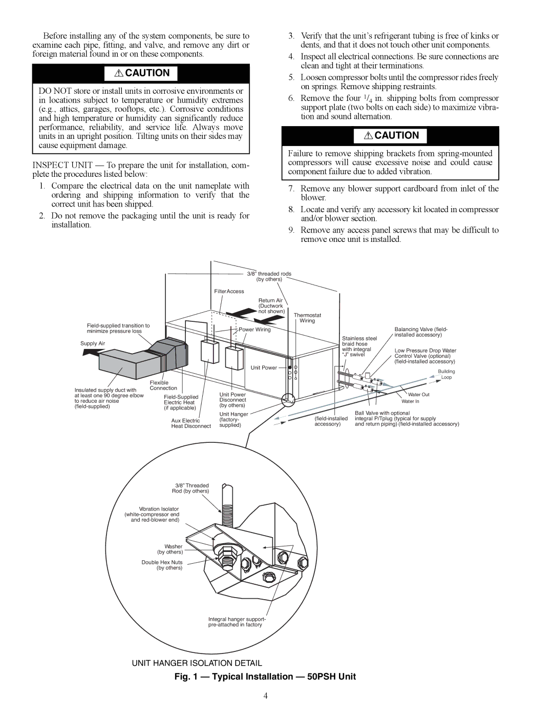
UNIT HANGER ISOLATION DETAIL
Fig. 1 — Typical Installation — 50PSH Unit
4