Chapter 1 Product Overview
Hardware Features
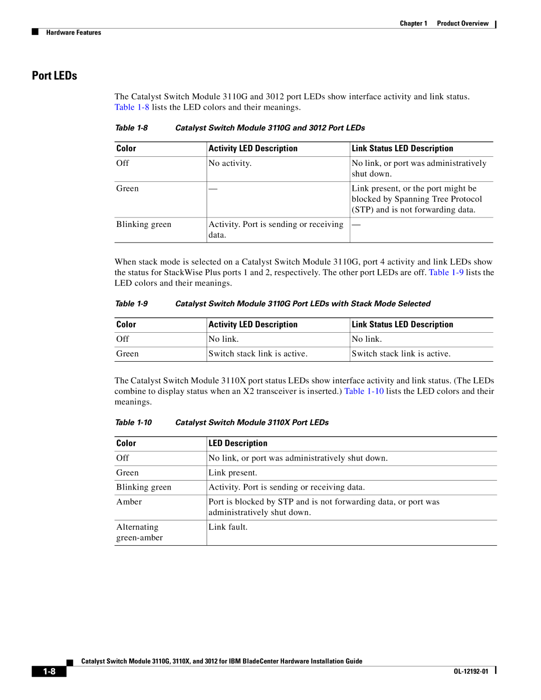
Port LEDs
The Catalyst Switch Module 3110G and 3012 port LEDs show interface activity and link status. Table
Table | Catalyst Switch Module 3110G and 3012 Port LEDs | ||
|
|
|
|
Color |
| Activity LED Description | Link Status LED Description |
|
|
|
|
Off |
| No activity. | No link, or port was administratively |
|
|
| shut down. |
|
|
|
|
Green |
| — | Link present, or the port might be |
|
|
| blocked by Spanning Tree Protocol |
|
|
| (STP) and is not forwarding data. |
|
|
|
|
Blinking green |
| Activity. Port is sending or receiving | — |
|
| data. |
|
|
|
|
|
When stack mode is selected on a Catalyst Switch Module 3110G, port 4 activity and link LEDs show the status for StackWise Plus ports 1 and 2, respectively. The other port LEDs are off. Table
Table | Catalyst Switch Module 3110G Port LEDs with Stack Mode Selected | ||
|
|
|
|
Color |
| Activity LED Description | Link Status LED Description |
|
|
|
|
Off |
| No link. | No link. |
|
|
|
|
Green |
| Switch stack link is active. | Switch stack link is active. |
|
|
|
|
The Catalyst Switch Module 3110X port status LEDs show interface activity and link status. (The LEDs combine to display status when an X2 transceiver is inserted.) Table
Table | Catalyst Switch Module 3110X Port LEDs | |
|
|
|
Color |
| LED Description |
|
|
|
Off |
| No link, or port was administratively shut down. |
|
|
|
Green |
| Link present. |
|
|
|
Blinking green |
| Activity. Port is sending or receiving data. |
|
|
|
Amber |
| Port is blocked by STP and is not forwarding data, or port was |
|
| administratively shut down. |
|
|
|
Alternating |
| Link fault. |
|
| |
|
|
|
Catalyst Switch Module 3110G, 3110X, and 3012 for IBM BladeCenter Hardware Installation Guide
| ||
|