April
Americas Headquarters
Cisco Systems, Inc 170 West Tasman Drive San Jose, CA
800 553-NETS Fax 408
Turn the television or radio antenna until the interference stops
C O N T E N T S
Hardware Features
Preface
Obtaining Documentation, Obtaining Support, and Security Guidelines
Using the Mode Button to Reset the Switch Module
Diagnosing Problems
Console Port
Verify Switch Module POST Results
Audience
Preface
Purpose
Conventions
Obtaining Documentation, Obtaining Support, and Security Guidelines
Related Publications
http//www-03.ibm.com/systems/bladecenter
viii
Switch Modules, page Hardware Features, page Management Options, page
Switch Modules
Switch Model
Product Overview
Switch Model
Hardware Features
Catalyst Switch Module 3110G, 3110X, and 3012 continued
Figure 1-1 Catalyst Switch Module 3110G and
Figure 1-2 Catalyst Switch Module
10/100/1000 Ethernet Ports
Chapter 1 Product Overview Hardware Features
OL-12192-01
Port Numbering
10-Gigabit Ethernet Module Slot
Internal 100BASE-T Ethernet Management Port
Port
Figure 1-3 Switch Module LEDs and Mode Button
Switch Module LEDs
System Power LED
Mode Button
Stack Master LED
Color
Fault LED
Fault/Stack Mode LED
Stack Mode Description
Fault Mode Description
Activity LED Description
Port LEDs
Link Status LED Description
LED Description
StackWise Plus Ports
Management Options
Console Port
Port Status LED Description
1-10
Network Configurations
Preparing for Installation
Switch Module Installation
Safety Warnings
Preparing for Installation, page Installing the Switch Module, page
Warning Class 1 laser product. Statement
Box Contents
Installation Guidelines
Figure 2-1 Blade Enclosure Rear-Panel View
Installing the Switch Module
After Installing the Switch Module
Stacking Guidelines
Creating Switch Stacks
Figure 2-3 Connecting the StackWise Plus Cables
Connecting a Switch Stack
Chapter 2 Switch Module Installation Creating Switch Stacks
Switch Stack Cabling Examples
OL-12192-01
203294
OL-12192-01
Chapter 2 Switch Module Installation Creating Switch Stacks
203295
Chapter 2 Switch Module Installation Creating Switch Stacks
2-10
OL-12192-01
203296
Installing an X2 Transceiver Module
Installing Devices in the 10-Gigabit Ethernet Slot
2-11
2-12
Removing a Module
Figure 2-7 Installing an X2 Transceiver Module
Where to Go Next
Connecting Devices to the Ethernet Ports
Device
Crossover Cable
Chapter 2 Switch Module Installation Where to Go Next
2-14
OL-12192-01
Diagnosing Problems
Troubleshooting
Verify Switch Module POST Results
Verify Switch Module LEDs
Bad or Damaged Cable
Verify Switch Module Connections
Ethernet and Fiber Cables
Link Status
Port and Interface Settings
Transceiver Issues
Ping End Device
Spanning Tree Loops
Verify Switch Module Performance
Resetting the Switch Module
Speed, Duplex, and Autonegotiation
Autonegotiation and Network Interface Cards
Using the Mode Button to Reset the Switch Module
How to Replace a Failed Stack Member
OL-12192-01
Chapter 3 Troubleshooting How to Replace a Failed Stack Member
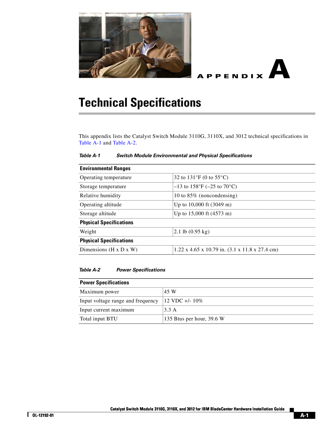
Physical Specifications
Technical Specifications
Power Specifications
A P P E N D I X A
OL-12192-01
Appendix A Technical Specifications
Connector Specifications
Connector and Cable Specifications
“Connector Specifications” section on page B-1
“Cable and Adapter Specifications” section on page B-2
10-Gigabit Ethernet Module Interface
Cable and Adapter Specifications
Four Twisted-Pair Cable Pinouts, page B-4
Two Twisted-Pair Cable Pinouts, page B-5
Transmit Power
10-Gigabit Ethernet X2 Transceiver Module Cable Specifications
Receive Power
Modal
Switch 1 TPO+ 2 TPO 3 TP1+ 6 TP1 4 TP2+ 5 TP2 7 TP3+ 8 TP3
Four Twisted-Pair Cable Pinouts
Four Twisted-Pair Straight-Through Cable Schematic
Figure B-5 Four Twisted-Pair Crossover Cable Schematic
Identifying a Crossover Cable
Two Twisted-Pair Cable Pinouts
Cable and Adapter Specifications
Appendix B Connector and Cable Specifications
OL-12192-01
I N D E
Numerics
IN-1
fault
IN-2
fault/stack mode
system power
IN-3
Index
IN-4
OL-12192-01