Chapter 5 Configuring the MGX
Establishing 1:N Redundancy Between Two or More
Note After you enter the addred command, the switch resets the secondary card; therefore, the secondary card will be unavailable for a few minutes.
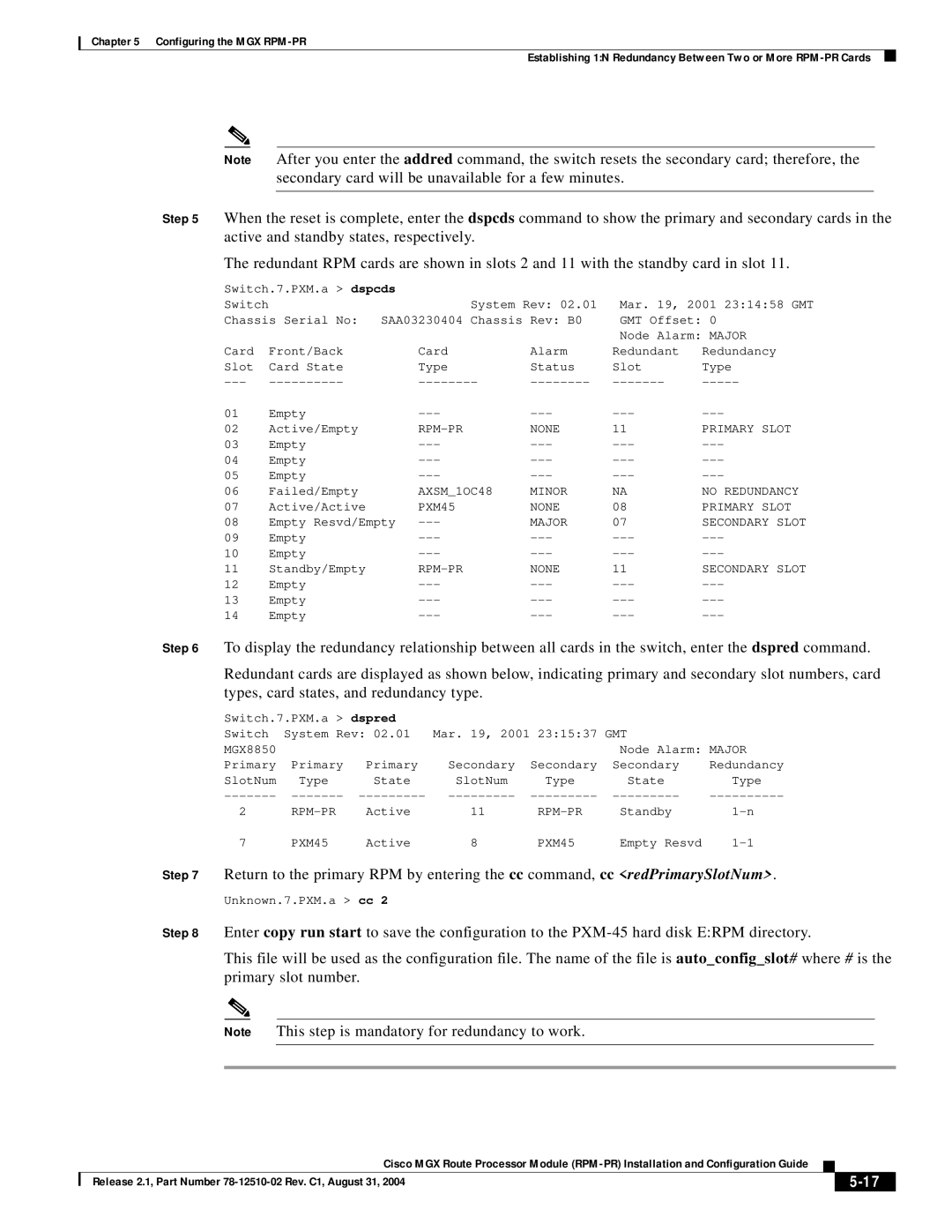
Step 5 When the reset is complete, enter the dspcds command to show the primary and secondary cards in the active and standby states, respectively.
The redundant RPM cards are shown in slots 2 and 11 with the standby card in slot 11.
Switch.7.PXM.a > dspcds |
|
|
|
| |
Switch |
| System Rev: 02.01 | Mar. 19, 2001 23:14:58 GMT | ||
Chassis Serial No: SAA03230404 Chassis Rev: B0 | GMT Offset: 0 | ||||
|
|
|
| Node Alarm: MAJOR | |
Card | Front/Back | Card | Alarm | Redundant | Redundancy |
Slot | Card State | Type | Status | Slot | Type |
01 | Empty | ||||
02 | Active/Empty |
| NONE | 11 | PRIMARY SLOT |
03 | Empty | ||||
04 | Empty | ||||
05 | Empty | ||||
06 | Failed/Empty | AXSM_1OC48 | MINOR | NA | NO REDUNDANCY |
07 | Active/Active | PXM45 | NONE | 08 | PRIMARY SLOT |
08 | Empty Resvd/Empty | MAJOR | 07 | SECONDARY SLOT | |
09 | Empty | ||||
10 | Empty | ||||
11 | Standby/Empty | NONE | 11 | SECONDARY SLOT | |
12 | Empty | ||||
13 | Empty | ||||
14 | Empty | ||||
Step 6 To display the redundancy relationship between all cards in the switch, enter the dspred command.
Redundant cards are displayed as shown below, indicating primary and secondary slot numbers, card types, card states, and redundancy type.
| Switch.7.PXM.a > dspred |
|
|
|
|
| |||
| Switch | System Rev: 02.01 | Mar. 19, 2001 23:15:37 GMT |
|
| ||||
| MGX8850 |
|
|
|
| Node Alarm: MAJOR | |||
| Primary | Primary | Primary | Secondary | Secondary | Secondary | Redundancy | ||
| SlotNum | Type | State | SlotNum | Type | State | Type | ||
|
| ||||||||
| 2 |
| Active | 11 | Standby | ||||
| 7 |
| PXM45 | Active | 8 | PXM45 | Empty Resvd |
| |
Step 7 | Return to the primary RPM by entering the cc command, cc <redPrimarySlotNum>. | ||||||||
| Unknown.7.PXM.a > cc 2 |
|
|
|
|
| |||
Step 8 | Enter copy run start to save the configuration to the | ||||||||
| This file will be used as the configuration file. The name of the file is auto_config_slot# where # is the | ||||||||
| primary slot number. |
|
|
|
|
| |||
|
|
|
|
|
|
| |||
| Note | This step is mandatory for redundancy to work. |
|
|
| ||||
|
|
|
|
|
|
|
|
|
|
|
|
|
|
|
|
|
|
|
|
Cisco MGX Route Processor Module
| Release 2.1, Part Number |
| |
|
|
