Verifying Installation
Verifying Installation
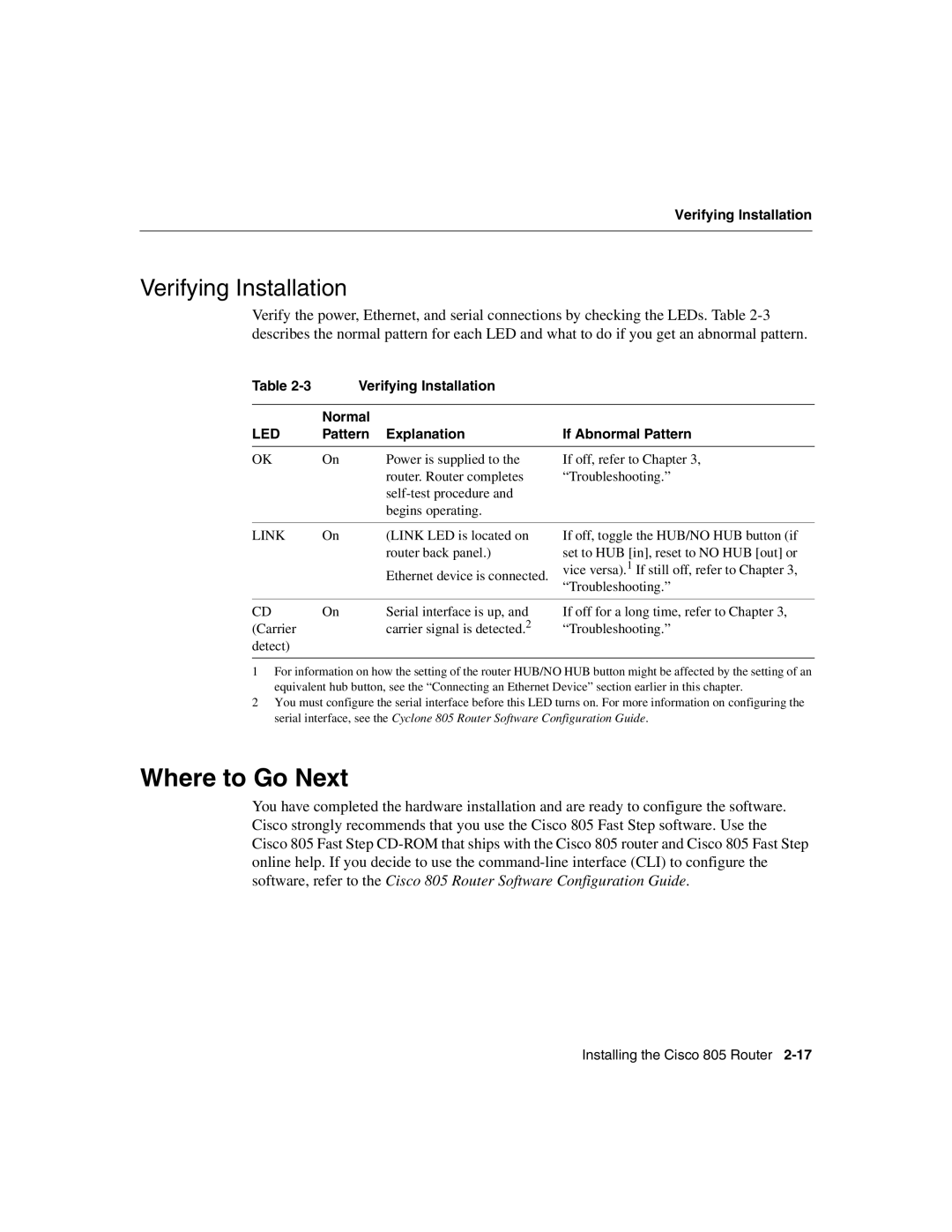
Verify the power, Ethernet, and serial connections by checking the LEDs. Table
Table 2-3 Verifying Installation
| Normal |
|
LED | Pattern Explanation | If Abnormal Pattern |
OK | On | Power is supplied to the |
|
| router. Router completes |
|
| |
|
| begins operating. |
If off, refer to Chapter 3, “Troubleshooting.”
LINK | On | (LINK LED is located on |
|
| router back panel.) |
|
| Ethernet device is connected. |
If off, toggle the HUB/NO HUB button (if set to HUB [in], reset to NO HUB [out] or vice versa).1 If still off, refer to Chapter 3, “Troubleshooting.”
CD | On | Serial interface is up, and |
(Carrier |
| carrier signal is detected.2 |
detect) |
|
|
If off for a long time, refer to Chapter 3, “Troubleshooting.”
1For information on how the setting of the router HUB/NO HUB button might be affected by the setting of an equivalent hub button, see the “Connecting an Ethernet Device” section earlier in this chapter.
2You must configure the serial interface before this LED turns on. For more information on configuring the serial interface, see the Cyclone 805 Router Software Configuration Guide.
Where to Go Next
You have completed the hardware installation and are ready to configure the software. Cisco strongly recommends that you use the Cisco 805 Fast Step software. Use the Cisco 805 Fast Step
Installing the Cisco 805 Router