Chapter 3 Installing the Router
Power Connections
Warning When stranded wiring is required, use approved wiring terminations, such as
Step 4 Remove the plastic covers from the terminal block. Save them for reinstallation after you finish wiring.
Note Do not remove the colored screw at either end of the terminal block. Those are the terminal mounting screws.
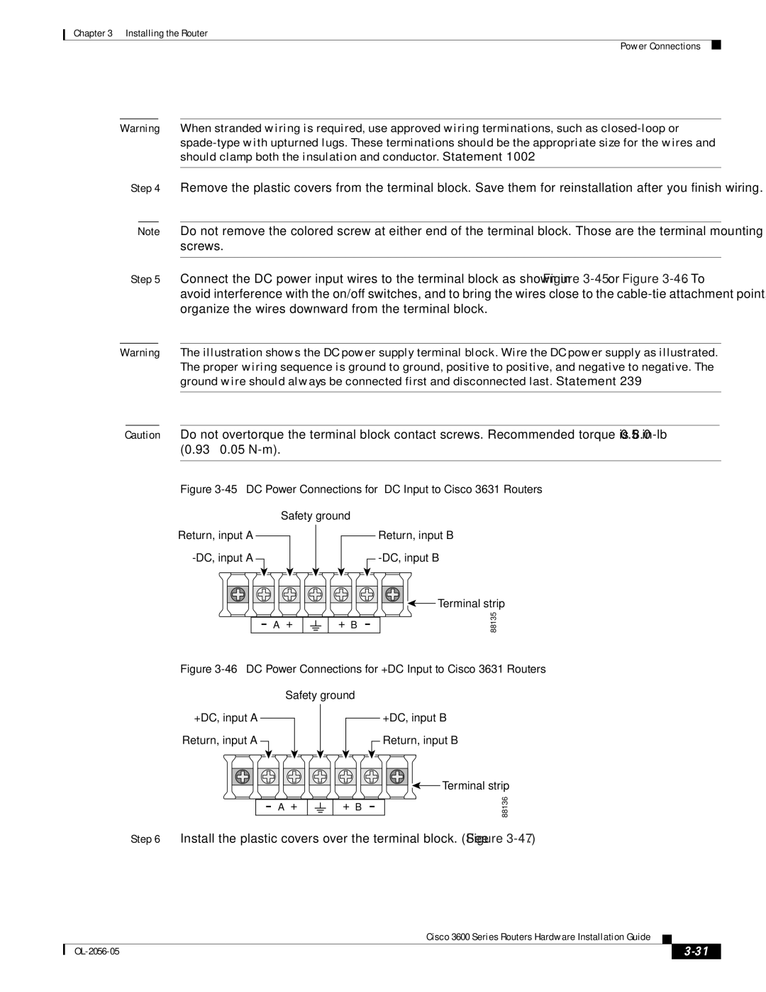
Step 5 Connect the DC power input wires to the terminal block as shown in Figure
Warning The illustration shows the DC power supply terminal block. Wire the DC power supply as illustrated. The proper wiring sequence is ground to ground, positive to positive, and negative to negative. The ground wire should always be connected first and disconnected last. Statement 239
Caution Do not overtorque the terminal block contact screws. Recommended torque is 8.0 ± 0.5
Figure 3-45 DC Power Connections for –DC Input to Cisco 3631 Routers
Safety ground
Return, input A
Return, input B
A+
+B
![]()
![]()
![]()
![]()
![]() Terminal strip
Terminal strip
88135
Figure 3-46 DC Power Connections for +DC Input to Cisco 3631 Routers
Safety ground
+DC, input A Return, input A
+DC, input B Return, input B
A+
+B
![]()
![]()
![]()
![]()
![]() Terminal strip
Terminal strip
88136
Step 6 Install the plastic covers over the terminal block. (See Figure
Cisco 3600 Series Routers Hardware Installation Guide
|
| ||
|
|