Chapter 1 | Introduction |
Power Supply
The Cisco ASR 901 router uses two 3 pin connectors (part number
The ground wire connects to a
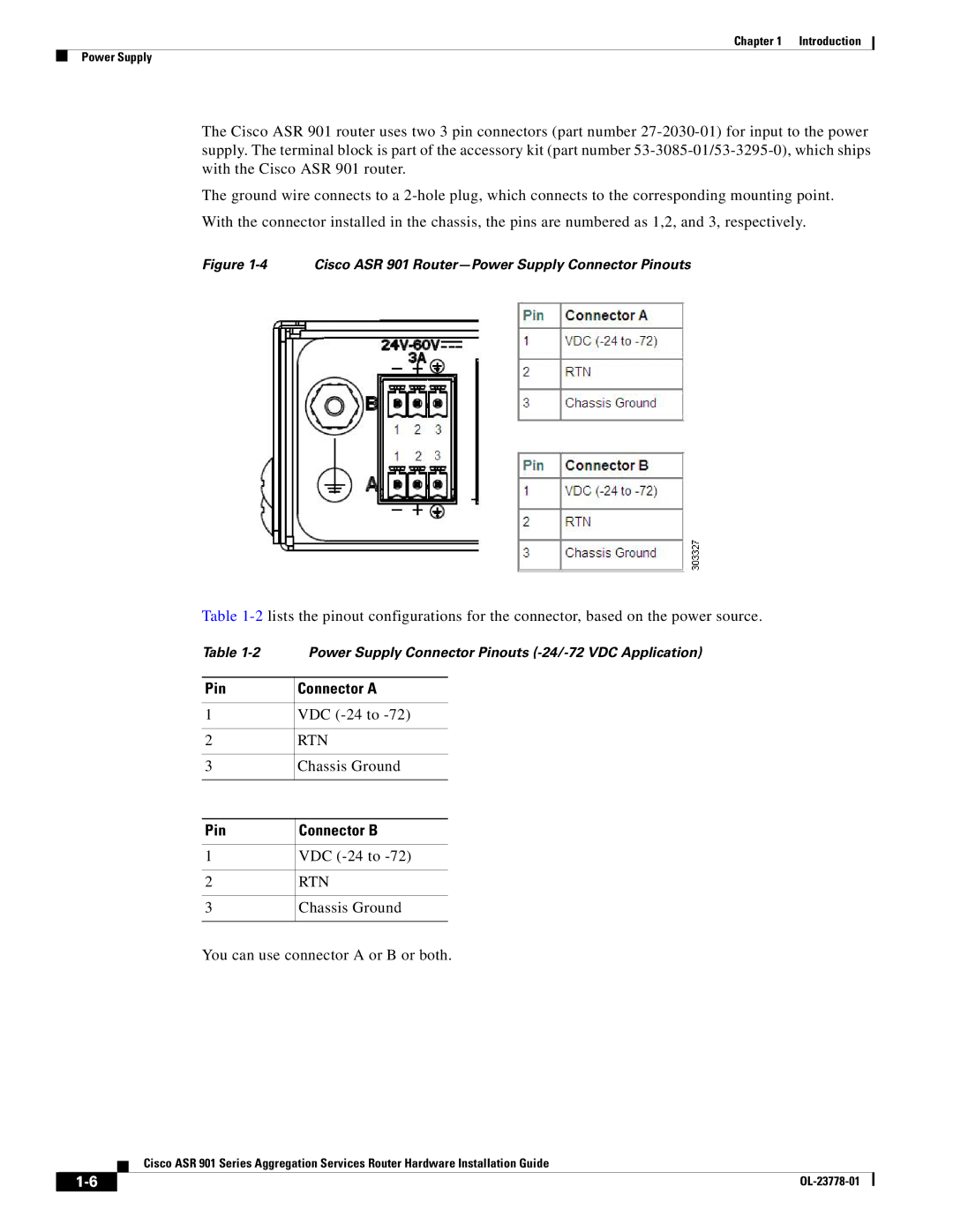
With the connector installed in the chassis, the pins are numbered as 1,2, and 3, respectively.
Figure 1-4 Cisco ASR 901 Router—Power Supply Connector Pinouts
Table
Table | Power Supply Connector Pinouts | |
|
|
|
Pin | Connector A | |
|
|
|
1 | VDC | |
|
|
|
2 | RTN | |
|
|
|
3 | Chassis Ground | |
|
|
|
|
|
|
Pin | Connector B | |
|
|
|
1 | VDC | |
|
|
|
2 | RTN | |
|
|
|
3 | Chassis Ground | |
|
|
|
You can use connector A or B or both.
Cisco ASR 901 Series Aggregation Services Router Hardware Installation Guide
|
| |
|