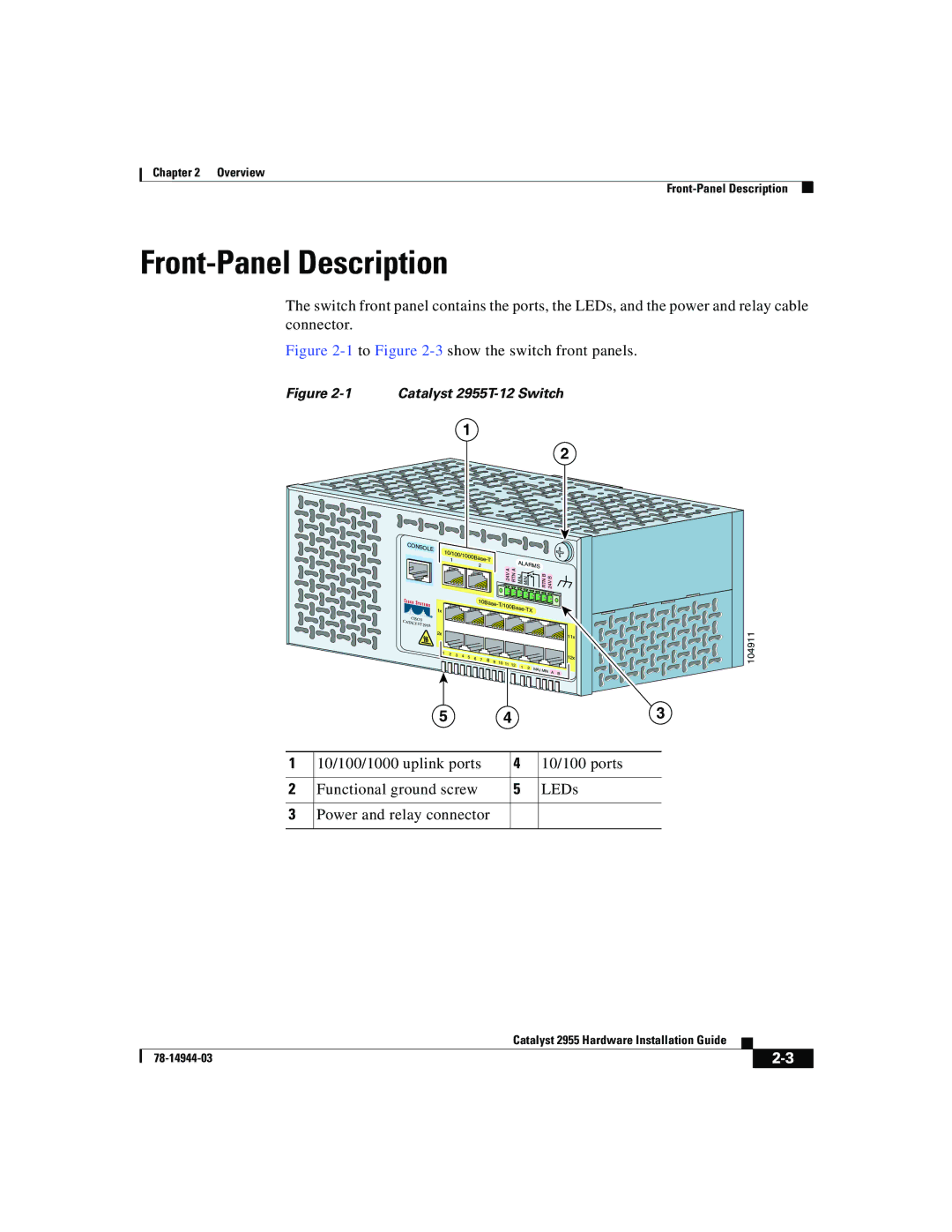
Catalyst 2955 specifications
The Cisco Systems Catalyst 2955 is a robust and versatile Ethernet switch designed for enterprises seeking reliable Layer 2 switching capabilities. Known for its steadfast performance and extensive feature set, the Catalyst 2955 is particularly favored for environments requiring high-density connectivity and advanced traffic management.One of the hallmark features of the Catalyst 2955 is its support for IEEE 802.1Q VLAN tagging, which allows for efficient traffic segregation and helps improve network security. The switch can handle up to 256 virtual LANs, supporting a more organized network structure and optimized resource allocation. This VLAN capability is crucial for businesses that need to segment their networks for various departments or applications while maintaining efficient communication between them.
The Catalyst 2955 is equipped with a comprehensive Quality of Service (QoS) mechanism, which prioritizes critical applications and ensures that voice, video, and data traffic receive appropriate bandwidth. By providing features such as classification, marking, queuing, and congestion avoidance, the switch helps meet the demands of real-time applications, thereby enhancing user experience and productivity.
Another remarkable technology integrated into the Catalyst 2955 is Spanning Tree Protocol (STP), which prevents loops in redundant network connections. Enhanced with features like Rapid Spanning Tree Protocol (RSTP), this switch minimizes downtime by allowing for quicker convergence times in case of topology changes. The ability to support both STP and RSTP is vital for maintaining network stability and performance.
The Catalyst 2955 is also designed with network management and monitoring in mind. It includes features like Simple Network Management Protocol (SNMP), which enables administrators to manage network resources effectively and troubleshoot issues more efficiently. With support for Cisco’s proprietary software, it offers insights into traffic patterns and usage statistics that can aid in maintaining optimal network health.
Physical characteristics of the Catalyst 2955 include various configurations with either 24 or 48 ports, suitable for different deployment scenarios. The switch is designed for rack mounting, making it an ideal solution for data centers and enterprise networks where space is a consideration.
In summary, the Cisco Systems Catalyst 2955 stands out for its solid Layer 2 functionality, VLAN support, QoS capabilities, network stability features such as STP, and extensive management tools, making it an excellent choice for organizations aiming to enhance network resiliency and performance. Its balance of performance and manageability continues to make it a viable option in the competitive landscape of networking equipment.

