Americas Headquarters
Cisco IOS XR Getting Started Guide
Cisco IOS XR Getting Started Guide
N T E N T S
Restrictions
Verifying the Spanning Tree
Routing Policy Language Line and Policy Limits
Contents CLI Tips and Shortcuts
Viii
Configuration Failures During a Commit Operation
About This Document
Changes to This Document
Revision Date Change Summary
Organization of the Document
Intended Audience
Related Documents
This document contains the following chapters
Conventions
Obtaining Documentation
Cisco.com
Convention
Cisco Product Security Overview
Documentation Feedback
Product Documentation DVD Ordering Documentation
Xii
Product Alerts and Field Notices
Reporting Security Problems in Cisco Products
Xiii
Cisco Technical Support & Documentation Website
Obtaining Technical Assistance
Xiv
Definitions of Service Request Severity
Submitting a Service Request
Obtaining Additional Publications and Information
Xvi
Supported Standalone System Configurations
Contents
Cisco CRS-1 Multishelf System Overview
Single-FCC Multishelf System
Two-FCC Multishelf System
Four-FCC Multishelf System
Router Management Interfaces
Command-Line Interface
Craft Works Interface
Extensible Markup Language API
Simple Network Management Protocol
Selecting and Identifying the Designated Shelf Controller
Selecting and Identifying the DSC on Cisco CRS-1 Routers
Connecting to the Router Through the Console Port
Communication Ports on the RP for a Cisco CRS-1 16-Slot LCC
Card status green=OK
Start the terminal emulation program Press Enter
To connect to the router, perform the following procedure
Log in to the router
Command or Action
Command or Action Purpose
Where to Go Next
If the router has no configuration, the router displays
If the router has been configured, the router displays
Software Requirements
Prerequisites
Hardware Prerequisites and Documentation
Bringing Up and Configuring a Standalone Router
Establish a connection to the DSC Console port
Return
Examples
Example
Verifying the System After Initial Bring-Up
Show version Command
Examples of show Commands
RP/0/RP0/CPU0router# show environment temperatures
Show environment Command
Show environment options
Show platform Command
Show redundancy Command
Multishelf System
Hardware Requirements
Restrictions
Bringup Overview
Information About Bringing Up a Multishelf System
Preparing a Rack Number Plan
DSC in a CRS-1/M-F1 Multishelf System
Chassis Serial ID Rack Number
Sample Rack Number Plan for a Two-FCC Multishelf System
Location of the Serial Number on a Fabric Card Chassis
Location of the Serial Number on a Line Card Chassis
Configuring the External Cisco Catalyst 6509 Switches
Software Requirements
Prerequisites
Hardware Requirements
Before You Begin
Restrictions
Quantity Description Part
Catalyst 6500 Sup720 Compact Flash Mem 256MB
Configuring the Catalyst Switches
Information About the Catalyst Switch Configuration
Revision number
Switchport access vlan
Sets the maximum-age timer for all MST instances on
Sets the forward-delay timer for all MST instances on
Sets the spanning tree priority for the switch
Primary Catalyst switch should be configured
Default selection
Example Single-FCC Multishelf System Configuration
Exits interface configuration mode and returns to global
Configuration mode
Switches in a four-FCC multishelf system
Example Four-FCC Multishelf System Configuration
CAT6k-2config# interface gigabitethernet 0/1
Router# show running-config
Switchport
Shutdown
Verify the Interface Status
Verifying the Catalyst Switch
CAT6k-1#show interfaces status
CAT6k-1#show spanning-tree
Verify that the Links are Not Unidirectional
Router# show interface gi 6/1 inc Gig
Prerequisites for an Integrated Switch System
Integrated Switch System
Information About the Integrated Switch Implementation
Restrictions for an Integrated Switch System
Integrated Switch Overview
Rack Type Description
Integrated Switch Functions
Integrated Switch Control Network Topology
Implementing the Integrated Switch System
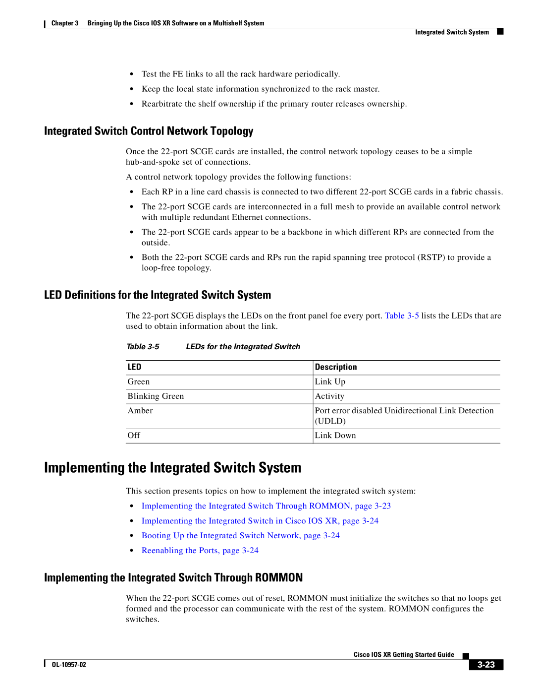
LED Definitions for the Integrated Switch System
Implementing the Integrated Switch Through Rommon
Booting Up the Integrated Switch Network
Implementing the Integrated Switch in Cisco IOS XR
6lists the Rommon switch configuration
Reenabling the Ports
Verifying the Control Ethernet Connection
Verifying the Port Statistics
Verifying Spanning Tree Protocol Information
Verifying Bidirectionality
Admin Configure Dsc serial serial ID rack
Bringing Up and Configuring Rack
Places the router in administration configuration mode
Planning information including DSC placement
LCC containing the DSC should be configured with
Want to configure as Rack
Enter this command for every FCC in the multishelf
When each subsequent LCC comes on line, the DSC
When each subsequent rack comes on line, the DSC
Commits the target configuration to the router running
Enter this command sequence for each of the eight fabric
Configures a plane to operate in an FCC slot
You want to configure
Fabric plane you are configuring. Valid slot numbers are
Group cisco-support
F0/SM0/FM
Bringing Up and Verifying FCCs
Apply power to all FCCs
Show controllers fabric rack all detail
Show controllers fabric plane all detail
Show controllers fabric rack all detail
Show controllers fabric connectivity all detail
Bringing Up and Verifying the Non-DSC LCC
Exit
Verifying the Spanning Tree
Enter this command for each RP and Scge card
Show platform command must be executed
Switched Interface column, one GE port
Expected Catalyst switch, as defined by the Catalyst
Verify the Spanning Tree
Detail location 1/rp0/cpu0
Detail location 0/rp1/cpu0
Detail location 1/rp1/cpu0
Detail location F0/SC0/cpu0
Verifying Fabric Cabling Connections
Detail location F0/SC1/cpu0
If the LED is off, it can mean
LED State Color Meaning
10 6 11 7
OIM11 OIM0
Where to Go Next
OL-10957-02
Chapter contains the following sections
Secure Domain Routers
3shows the DRP Plim connections
Connecting and Communicating with the Router
Remote CLI, CWI XML, or Snmp
Card status green=OK
Communication Ports on the DRP Plim
Establishing a Connection Through the Console Port
Summary Steps
Standalone router is starting up for the first time, see
Establishing a Connection Through a Terminal Server
Standalone Router. If a multishelf system is starting
Up for the first time, see , Bringing Up
Press Enter Log in to the router
Install and configure the terminal server
Root-system username and password when prompted
Replace access-server-address with the IP address
Establishes a Telnet session with the terminal server
Terminal server, and replace port with the terminal
Telnet ManagementEthernetInterfaceIPaddress
Logging In to a Router or an SDR
Prompt Syntax Components Description
CLI Prompt
User Groups, Task Groups, and Task IDs
User Access Privileges
Predefined User Groups
Command Description
User Group Privileges
Personnel
Show user all
Show user tasks
Show aaa usergroup group-name
User group root-system Inherits from task group Root-system
Aaa usergroup root-system
Navigating the Cisco IOS XR Command Modes
Command Mode Navigation Example,
Identifying the Command Mode in the CLI Prompt
Command Mode Description
Summary of Common Command Modes
Example
Not available on most routers
Password recovery, and other diagnostic tasks
Entering Exec Commands from a Configuration Mode
Command Mode Navigation Example
6illustrates the two-stage configuration process
Managing Configuration Sessions
RP/0/RP0/CPU0router# show configuration sessions
Displaying the Active Configuration Sessions
RP/0/RP0/CPU0routerconfig-if#ipv4 address 10.10.10.10
Starting a Configuration Session
Displaying Configuration Details with show Commands
Starting an Exclusive Configuration Session
Displaying the Running Configuration
Following sections describe the following tasks
Ntp
Displaying a Sanitized Version of the Running Configuration
Telnet ipv4 server max-servers 5 username removed
Displaying the Target Configuration
Displaying a Combined Target and Running Configuration
Configuration failed load command
Displaying Configuration Error Messages and Descriptions
Loading the Target Configuration from a File
Saving the Target Configuration to a File
Loading an Alternative Configuration at System Startup
Committing Changes to the Running Configuration
Clearing All Changes to a Target Configuration
Commit best-effort
Show configuration commit list detail command
Commit comment line
Commit confirmed
RP/0/0/CPU0routerconfig# load configuration failed commit
Reloading a Failed Configuration
Returning Directly to Configuration Mode from a Submode
Exiting a Configuration Submode
Ending a Configuration Session
Aborting a Configuration Session
Configuring the SDR Hostname
Preceding example sets the SDR name to Sdrsj
Syntax Components Description
Configuring the Management Ethernet Interface
Management Interface Interface Name Example
Displaying the Available Management Ethernet Interfaces
Configure Interface MgmtEthrack/slot/CPU0/port
Configuring the Management Ethernet Interface
Prerequisites
Enters interface configuration mode and specifies
Enters global configuration mode
Command parameters are described in Table
Exits the Management Ethernet interface configuration
Displays the interface details to verify the settings
Ends the configuration session and returns to Exec
RP/0/RP0/CPU0routerconfig-if#ipv4 address 10.1.1.1
Show interfaces MgmtEth rack/ slot/CPU0/ port
Clock update-calendar Show clock
Manually Setting the Router Clock
Related Topic Document Title
Commit End
Enter the show clock command
Clock timezone command should be entered
For detailed information about setting the system
Clock, including the configuration of a network time
Related Documents
Configuring Additional Router Features
Following example, the domain name and DNS are configured
Configuring Telnet, HTTP, and XML Host Services
Complete descriptions of the domain services
Commands
Following example, the host services are enabled
Managing Configuration History and Rollback
Installation and activation of the Manageability
Descriptions of the Telnet commands
RP/0/RP1/CPU0router# show configuration commit list
Displaying the Configuration Changes Recorded in a CommitID
RP/0/RP1/CPU0routeradmin# show configuration commit list
Displaying the CommitIDs
RP/0/RP1/CPU0routeradmin# show configuration commit changes
Previewing Rollback Configuration Changes
RP/0/RP1/CPU0router# show configuration rollback changes to
RP/0/RP1/CPU0router# rollback configuration to
Rolling Back the Configuration to a Specific Rollback Point
RP/0/RP0/CPU0router# rollback configuration last
RP/0/RP1/CPU0router# show configuration commit changes ?
RP/0/0/CPU0routerconfig# load rollback changes
RP/0/0/CPU0routerconfig# load rollback changes to
RP/0/0/CPU0router# clear configuration commit diskspace
Deleting CommitIDs
Logging Destination Command Global Configuration Mode
Configuring Logging and Logging Correlation
Logging Locations and Severity Levels
Level Description
Configuring Basic Message Logging
Alarm Logging Correlation
Logging trap severity Logging console severity
Commit End Show logging
RP/0/RP0/CPU0routerconfig# logging trap debugging Levels
RP/0/RP0/CPU0routerconfig# logging
When a severity level is specified, only messages at
Specifies a syslog server host to use for system logging
Configuration of system logging
Following example, basic message logging is configured
Commands used to configure logging
Configuration of alarm correlation and generating
Creating and Modifying User Accounts and User Groups
Creating Users and Assigning Groups
Configuring User Accounts
Specifies a password for the user named in Step
Enters username configuration submode
Use the secret command to create a secure login
Password for the user names specified in Step
Static Route Configuration Limits
Configuration Limiting
Default Absolute Configuration Command
Limit Mode
OSPFv2 and v3 Configuration Limits
IS-IS Configuration Limits
Limit Mode Exec Mode
Maximum-redistributed-prefixes n Show isis adjacency
Maximum interfaces n Show ospf
Maximum paths n Show running-config router ospf
Maximum redistributed-prefixes Show ospf
If the maximum paths
Maximum Routes Redistributed into Ospf
Default Absolute Maximum Configuration Command
BGP Configuration Limits
Feature Limit Description
Routing Policy Language Line and Policy Limits
RP/0/RP1/CPU0router# show rpl maximum
Mpls Configuration Limits
Multicast Configuration Limits
Default Absolute Show Current Settings Maximum Command
Limit Configuration Command Exec Mode
Other Configuration Limits
CLI Tips and Shortcuts
CLI Tips, Techniques, and Shortcuts
Using the Question Mark ? to Display On-Screen Command Help
Entering Abbreviated Commands
Generally, uppercase letters represent variables arguments
That apply to the keyword and brief explanations
Identifying Command Syntax Errors
Completing a Partial Command with the Tab Key
Using the no Form of a Command
Displaying System Information with show Commands
Editing Command Lines that Wrap
Command Description Command Mode
Common show Commands
Halting the Display of Screen Output
Browsing Display Output when the --More-- Prompt Appears
RP/0/RP1/CPU0router# show running-config router static
Narrowing Output from Large Configurations
Redirecting Output to a File
Using Wildcards to Display All Instances of an Interface
Filtering show Command Output
RP/0/RP1/CPU0router# show running-config interface pos
Contains the regular expression
Adding a Filter at the --More-- Prompt
Displays output lines that contain the regular expression
File on the specified device
Wildcards, Templates, and Aliases
Using Wildcards to Identify Interfaces in show Commands
Example
Wildcard Syntax Description
RP/0/RP1/CPU0router# show interfaces pos* brief
Creating Configuration Templates
End-template
Show running-config template template-name
Applies the target configuration commands to the running
Applying Configuration Templates
RP/0/RP0/CPU0router# show running-config Template tmplt1
Show running-config template template-name
Aliases
5defines the alias command syntax
Keystrokes Used as Command Aliases
Command History
Displaying Previously Entered Commands
RP/0/0/CPU0routerconfig# alias my-cookie mgmtEth 0/0/CPU0/0
Redisplaying the Command Line
Recalling Previously Entered Commands
Command or Key Combination Purpose
Command or Key Combination Recalls
Key Combinations to Move the Cursor
Key Combinations
Keystrokes to Control Capitalization
Keystrokes Function Moves the Cursor
Transposing Mistyped Characters
Keystrokes to Delete CLI Entries
Esc, L Esc, U
Keystrokes Deletes
OL-10957-02
Additional Sources for Information
Basic Troubleshooting Commands
Show install
Show variables boot
Show context and show exception
Show controller
Using the ping Command
Following example, a successful ping attempt is shown
Using the traceroute Command
Next example, an unsuccessful ping attempt is shown
Displaying a List of Debug Features
Using debug Commands
Following example, the route for an IP address is displayed
RP/0/RP0/CPU0router# traceroute
Displaying Debugging Status
Enabling Debugging for a Feature
Disabling Debugging for a Service
Configuration Error Messages
Configuration Errors at Startup
Configuration Failures During a Commit Operation
Show configuration failed command
Show configuration failed noerror command
Understanding Low-Memory Warnings in Configuration Sessions
Memory Warnings in Configuration Sessions
Displaying System Memory Information
ERROR! Memory is in Severe or Critical State
Clearing a Target Configuration
Removing Configurations to Resolve Low-Memory Warnings
Removing Committed Configurations to Free System Memory
Heading Description
Clearing Configuration Sessions
Rolling Back to a Previously Committed Configuration
Contacting TAC for Additional Assistance
Interfaces Not Coming Up
Verifying the System Interfaces
RP/0/RP0/CPU0router# show ipv4 interface brief
Configure the interfaces, as shown in the following examples
Connection
Bring the interface up with the following commands
OL-10957-02
Regular Expressions
Character Pattern Ranges
Special Characters
Character Special Meaning
Multiple-Character Patterns
Complex Regular Expressions Using Multipliers
Character Description
Ba?b
Anchor Characters
Pattern Alternation
Underscore Wildcard
Parentheses Used for Pattern Recall
Bc.\1\2
OL-10957-02
GL-1
Denoted as primary
Is from 0x0 to 0xFFFF 0 to 65535 in decimal
Into memory at startup
Processes
Client runs in a web browser
Have a registered name in the same style
Installation or upgrade
Outgoing channel
Received
Need to provide continuous service
Examples of platforms using a GUI. See also CLI
GL-4
RIP
Provides other information relevant to IP packet processing
GL-5
048,576 bits
To boot a node
Standard and private proprietary branches
IP routing information
Battery permanently connected
Card installed and running on the router
Loading software images from a network server, such as Tftp
Sent to it by a peer
Interfaces connecting to a Cisco CRS-1 router
Group of software components installed on the router
SDH frames
GL-8
Data
Delay, and delivery guarantee
GL-9
GL-10
GL-11
Cisco Technical Assistance Center
GL-12
GL-13
GL-14
IN-1
Multicast
IS-IS
Static routes
IN-2
RP for 4-slot and 8-slot LCCs, illustration 1-11,4-4
DRP Plim illustration PRP-2 illustration
IN-3
IN-4
Low memory warning, removing configurations
Module Number displayed in prompt More prompt
Maximum-paths command
IN-5
IN-6
FCC
IN-7
Show tech-support command 6-6,7-3 Show user command
Show task supported command
Status LEDs
IN-8
Wildcards
Username command
IN-9
IN-10