Appendix C Connecting to DC Power
Wiring the
Warning Only trained and qualified personnel should be allowed to install or replace this equipment.
Statement 1030
Caution You must connect the Cisco ME DC switch only to a
Caution The Cisco ME
To wire the switch to a
Step 1 To ensure that all power is OFF, locate the circuit breaker on the panel board that services the DC circuit, switch the circuit breaker to the OFF position, and tape the switch handle of the circuit breaker in the OFF position.
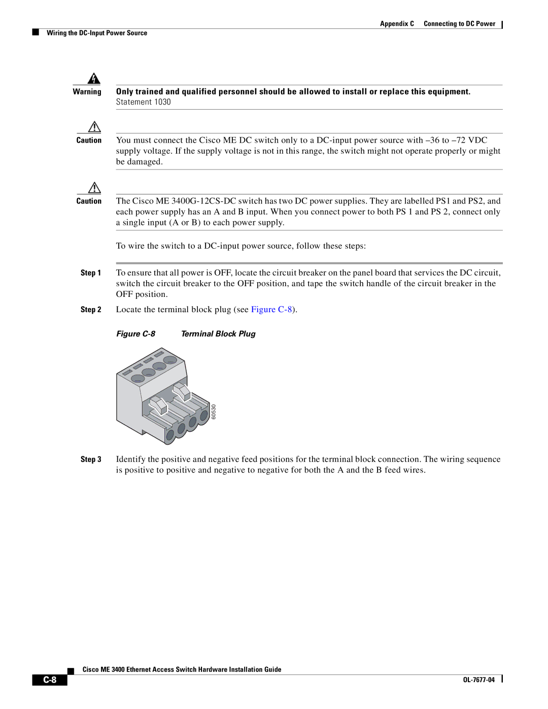
Step 2 Locate the terminal block plug (see Figure
Figure C-8 Terminal Block Plug

![]() 60530
60530
Step 3 Identify the positive and negative feed positions for the terminal block connection. The wiring sequence is positive to positive and negative to negative for both the A and the B feed wires.
Cisco ME 3400 Ethernet Access Switch Hardware Installation Guide
|
|
| |
|
|