Appendix C Connecting to DC Power
Wiring the
Complete these steps:
Step 1 Remove all paint or oxidation from the rack at the point of the grounding connection.
Step 2 Use a
Step 3 Connect the wire to a ring lug (large enough for the rack screw to fit through).
Step 4 Use a
Step 5 Tighten the grounding screw on the rack over the ring lug.
Repeat these steps for each switch being installed.
Wiring the DC-Input Power Source
Before you wire the
If the switch software detects that the circuit boards are not receiving power from an internal power supply, the software sends a message like this to the console:
00:06:54:
00:06:54:
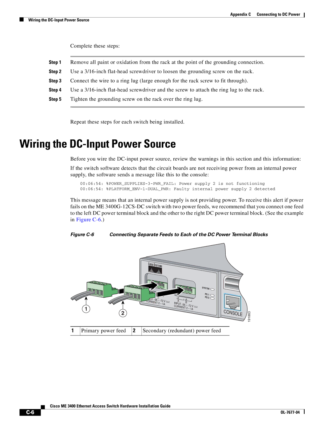
This message means that an internal power supply is not providing power. To receive this alert if power fails on the ME
Figure C-6 Connecting Separate Feeds to Each of the DC Power Terminal Blocks
|
|
|
|
|
|
|
|
| SYSTEM |
|
|
|
|
|
| B |
| + |
| PS 1 |
|
| |
|
|
|
| + | PS 2 |
|
| ||||
|
|
|
| – | A |
|
|
| |||
|
|
| CURRENT | B |
|
|
| ||||
|
|
| 2 – 1A | INPUT |
|
|
| ||||
|
|
|
|
| – |
|
| ||||
| 1 |
|
|
|
|
| CURRENT |
|
|
| |
|
|
|
|
|
|
| 2 – 1A | CONSOLE |
| ||
| 2 |
|
|
|
|
|
|
|
| 191863 | |
|
|
|
|
|
|
|
|
|
|
| |
1 | Primary power feed | 2 | Secondary (redundant) power feed |
|
| ||||||
Cisco ME 3400 Ethernet Access Switch Hardware Installation Guide
|
|
| |
|
|
