Cisco MDS 9000 Family NX-OS Interfaces Configuration Guide
Americas Headquarters
Page
N T E N T S
TL Ports
Specifying a Port Owner
Configuring Fibre Channel Interfaces
Information About Interface Buffers
Default Settings
Deleting an Interface from a PortChannel
Verifying NPV
Monitoring Ports in a Vsan
Xii
Port Monitor Configuring Port Added information about 22a
Enhancements Monitor Policy Feature Port Monitor Port Guard
Three new counters for the port Monitor command
About This Guide
FlexAttach
Monitoring Monitoring a selected port group
Enhancements
Audience
Organization
Chapter Title Description
Document Conventions
Boldface font
Related Documentation
Command-Line Interface
Troubleshooting and Reference
Trunks and PortChannels
Fibre Channel Port Rate Limiting
Extended Credits
Port Virtualization
FlexAttach
Interfaces Overview FlexAttach
OL-29284-01, Release
Configuring Interfaces
Information About Interfaces
Interface Description
Interface Modes
Port
FL Port
NP Ports
TL Port
TE Port
TF Port
Auto Mode
TNP Port
SD Port
ST Port
Administrative States
Interface States
Operational States
Reason Codes
Administrative Operational Configuration Status Reason Code
None
Reason Codes for Interface States
Applicable
Reason Code long version Description Modes
Reason Codes for Nonoperational States
Graceful Shutdown
Port Administrative Speeds
Frame Encapsulation
Autosensing
Bit Error Thresholds
Cisco MDS 9000 Family Switch Interface Modes
Beacon LEDs
Speed LEDs
SFP Transmitter Types
Extended transmitters assigned to Cisco-supported SFPs
SFP Transmitter Acronym Definitions
TL Ports
CWDM-1590 CWDM-1610 C1590 C1610
Translation from Translation to Example
Supported TL Port Translations
TL Port Alpa Caches
Port Guard
Port Monitor
Threshold Interval Rising Falling Counter Type Seconds Event
Local Switching
Port Monitor Port Guard
Port Group Monitor
Rising Threshold
Slow Drain Device Detection and Congestion Avoidance
Management Interfaces
Generation 1 Interface Configuration Guidelines
Prerequisites for Interfaces
Guidelines and Limitations
Vsan Interfaces
Private Loop Configuration Guidelines
Vsan Interface Configuration Guidelines
Default Settings
Configuring Interfaces
7lists the default settings for interface parameters
Parameters Default
Configuring Fibre Channel Interfaces
Command Purpose
Setting the Interface Administrative State
Configuring Interface Modes
Configuring System Default Port Mode F
Sets the administrative mode of Fibre Channel ports to
Mode F if applicable
Default unless user configured
Configuring ISL between Two Switches
Configuring 10-Gbps FC Mode
Configuring Port Administrative Speeds
Configuring Port Speed Group
Configuring the Interface Description
Configuring Beacon Mode
Enters configuration mode
Interface configuration submode
Specifying a Port Owner
Disabling Bit Error Threshold
Configuring Switch Port Attribute Default Values
Configuring TL Ports
Configures manual entries into the Alpa cache
Manually Inserting Entries into the Alpa Cache
Clearing the Alpa Cache
Configuring Port Guard
Configuring Port Monitor
To enable port monitor, follow these steps
Enables default port monitoring
Disables port monitoring
Configuring a Port Monitor Policy
Specifies the delta protocol error poll interval
Specifies the delta signal loss poll interval
Reverts to the default policy for sync loss
Reverts to the default policy for Tx performance
Configuring a Port Monitor Port Guard
Configuring Port Group Monitor
Activating a Port Monitor Policy
Configuring a Port Group Monitor Policy
Enabling Port Group Monitor
Reverting to the Default Policy for a Specific Counter
Turning Off the Monitoring of Specific Counter
Configuring Management Interfaces
Activating a Port Group Monitor Policy
Creating Vsan Interfaces
Configuring Congestion Frame Timeout Value
Configuring Stuck Frame Timeout Value
Configuring No-Credit Timeout Value
Configuring Credit Loss Recovery Threshold and Action
Specifies the no-credit timeout value and port
Mode for the switch
Specifies the default no-credit timeout value port
Verifying Interfaces Configuration
Configuring Interfaces Verifying Interfaces Configuration
Discards, 0 errors
Displaying Interface Information
Example 2-3 Displays All Interfaces
Example 2-4 Displays Multiple, Specified Interfaces
Interface fc1/1 5 , fc2/5
Interface fc3/13 , fc3/16
Switch# show interface fc2/2 fc2/2 is trunking
Example 2-5 Displays a Specific Interface
Frames/sec
Switch# show interface description
Switch# show interface brief
Example 2-6 Displays Port Description
Switch# show interface counters fc3/1
Example 2-8 Displays Interface Counters
Switch# show interface counters brief
Example 2-9 Displays Interface Counters in Brief Format
Switch# show running-config
Example 2-10 Displays Transceiver Information
Switch# show running-config interface fc1/1
System default switchport mode F interface fc4/1
Switch# show tlport list
Displaying TL Port Information
Example 2-17 Displays the TL Ports in All VSANs
Displaying the Alpa Cache Contents
Displaying Port Monitor Status and Policies
Switch# show port-monitor
Port-monitor active
Switch# show port-group-monitor status
Displaying Port Group Monitor Status and Policies
Switch# show port-group-monitor
Default
Pgm1
Pgm2
Displaying Management Interface Configuration
Switch# show interface mgmt 0 mgmt0 is up
Displaying Vsan Interface Information
OL-29284-01, Release
Generations of Modules and Switches
Information About Fibre Channel Interfaces
Generation 3 Fabric Switch
Part Number Product Name and Description
Backplane crossbar bandwidth
Any-to-any connectivity
Generation 2 Fabric Switches
Port Groups
Maximum
Product Name
Generation 3 Fabric Switches
DS-C9148-K9 Port 8-Gbps Cisco MDS Fabric switch
Part Number Description Per Port Group Gbps
Generation 3 Modules
Port Rate Modes
Supports Default Speed Product Name
Mode and Rate
Switches
Dedicated Rate Mode
Part Number Description Mode Mode on All Ports
Configured Speed Reserved Bandwidth
Auto Gbps Auto with 4-Gbps maximum
Shared Rate Mode
Auto Gbps Auto with 2-Gbps maximum
Dedicated Rate Mode Configurations for the 8-Gbps Modules
Modules
Port Speed
Dynamic Bandwidth Management
Negotiates to a maximum speed of 4 Gbps
Negotiates to a maximum speed of 8 Gbps
Out-of-Service Interfaces
Oversubscription Ratio Restrictions
Switch# show port-resources module 8 Module
Bandwidth Allocation for Oversubscribed Interfaces
Switch# show port-resources module
Fc5/12 Shared Port-Group Total bandwidth is 32.4 Gbps
Fc5/31
Buffers Gbps
Upgrade or Downgrade Scenario
Switch# show module 2 bandwidth-fairness
Bandwidth Fairness
Guidelines and Limitations
Local Switching Limitations
Switch# show port index-allocation
Port Index Limitations
Switch# show module
Number of Port Indexes Required
Generation 1 Module Supervisor-1 Module Supervisor-2 Module
Port Index Requirements for Generation 1 Modules
PortChannel Limitations
PortChannels have the following restrictions
Show port index-allocation startup
Cisco MDS 9000 Family NX-OS Interfaces Configuration Guide
PortChannel Configuration and Addition Results
PortChannel
New Member Members PortChannel Type Addition Type Result
If resources are not available
Default Port 4-Gbps Port 10-Gbps Parameter Switching Module
Speed mode Auto Auto1 Rate mode Shared
Auto
Shared Dedicated
Configuring Fibre Channel Interfaces
Port mode BBcredit buffers
14 Default Generation 4 Interface Parameters
Configure the rate mode dedicated or shared
Configure the port mode
Configure the rate mode dedicated or shared to use
Task Flow for Configuring 12-Port 4-Gbps Module Interfaces
Task Flow for Configuring 4-Port 10-Gbps Module Interfaces
Configuring Port Speed
Configuring Rate Mode
Switch# show interface fc 9/1 fc9/1 is up
Displaying the Rate Mode Configuration for Interfaces
Port-resources command to
Switch# show port-resource module 4 Module
Fc4/1232 8.0 shared Port-Group Total bandwidth is 12.8 Gbps
Switch# show port-resources module 7 Module
Fc7/13
Configuring Local Switching
Disabling Restrictions on Oversubscription Ratios
Buffers Gbps Fc2/1 Shared Fc2/2 Fc2/3
Switch# show running-config include oversubscription-limit
Switch# copy running-config startup-config
Enabling Restrictions on Oversubscription Ratios
Shut down
Enabling Bandwidth Fairness
Taking Interfaces Out of Service
Configuration submode
Disabling Bandwidth Fairness
Selects the interface and enters interface
Disables the interface
Takes the interface out of service
Fc9/2 out-of-service
Releasing Shared Resources in a Port Group
Verifying Fibre Channel Interfaces Configuration
Disabling ACL Adjacency Sharing for System Image Downgrade
Switch# show interface fc 9/1 capabilities
Switch# show interface fc 4/1 capabilities
Displaying Interface Capabilities
Configuration Examples for Fibre Channel Interfaces
Displaying SFP Diagnostic Information
Configuration Example for 48-Port 8-Gbps Module Interfaces
Configuration Example for 24-Port 8-Gbps Module Interfaces
Enable the interfaces and return to configuration mode
Select the interfaces fc 4/3 through fc 4/4
Disable the interfaces and take them out of service
Return to configuration mode
Select interfaces fc 3/1
Select the interfaces fc 3/2 through fc 3/3
Configuration Example for 48-Port 4-Gbps Module Interfaces
Switchconfig# interface fc 4/2
Select the interfaces fc 4/2 through fc 4/10
Select the interfaces fc 4/1 through fc 4/6
Configuration Example for 24-Port 4-Gbps Module Interfaces
Select the interfaces fc 4/7 through fc 4/10
Select the interfaces fc 3/4 through fc 3/6
OL-29284-01, Release
Information About Interface Buffers
Buffer-to-Buffer Credits
Performance Buffers
Buffer Pools
Total BB credit buffers
189047
BBCredit Buffers for Switching Modules
Shared Rate Mode
BBCredit Buffers Per Port
Gbps Speed BBCredit Buffer Allocation
Fx Port
Default BBcredit buffers 250 Maximum BBcredit buffers 500
Port 8-Gbps Switching Module BBCredit Buffer Allocation
Default BBcredit buffers 500 Maximum BBcredit buffers
24-Port 8-Gbps Switching Module BBCredit Buffer Allocation
Total Number of BBCredit Buffers per Module
Ports 1 through Ports 13 through 6000
Three ports with dedicated rate mode and 4-Gbps speed
4/44-Port 8-Gbps Switching Module BBCredit Buffer Allocation
Dedicated Rate Mode
48-Port 4-Gbps Switching Module BBCredit Buffer Allocation
Gbps Speed
Gbps
24-Port 4-Gbps Switching Module BBCredit Buffer Allocation
Port 4-Gbps Fibre Channel Module BBCredit Buffers
Port 4-Gbps Switching Module BBCredit Buffers
12-Port 4-Gbps Switching Module BBCredit Buffer Allocation
Gbps Speed BBCredit Buffer Allocation Type ISL Fx Port
ISL
Port 10-Gbps Switching Module BBCredit Buffers
4-Port 10-Gbps Switching Module BBCredit Buffer Allocation
Gbps Speed BBCredit Buffer Allocation Type
Port
BBCredit Buffers for Fabric Switches
Cisco MDS 9148 Fabric Switch BBCredit Buffers
Cisco MDS 9134 Fabric Switch BBCredit Buffers
Port 8-Gbps Fabric Switch BBCredit Buffer Allocation
Cisco MDS 9124 Fabric Switch BBCredit Buffers
User-configurable BBcredit buffers 4509 250
MDS 9124 Fabric Switch BBCredit Buffer Allocation Defaults
Extended BBCredits
Extended BBcredits on Generation 1 Switching Modules
Port Group Support for the Extended BBCredits Feature
OL-29284-01, Release
Buffer-to-Buffer Credit Recovery
Buffer-to-Buffer State Change Number
Configuring Interface Buffers
Configuring Buffer-to-Buffer Credits
Receive Data Field Size
Configuring Performance Buffers
Configuring Extended BBcredits
Enabling Buffer-to-Buffer Credit Recovery
Configuring Receive Data Field Size
Enabling the Buffer-to-Buffer State Change Number
Verifying BBCredit Configuration
Interface to 2000 bytes. The default is
Reduces the data field size for the selected
Bytes and the range is from 256 to 2112 bytes
Cisco MDS 9000 Family NX-OS Interfaces Configuration Guide
Information About Trunking
Trunking E Ports
Trunking F Ports
Link Number Link Description
1a and 1b Port trunk with N port Port trunk with NP port
Trunking NP port with third-party core switch F port
Key Concepts
Trunking Protocols
PortChannnel with NP port
Trunk Link Default
Your Trunk Mode Configuration
Port Type Switch Trunking State Port Mode
Port Type Core Switch NPV Switch Trunking State Link Mode
Trunk-Allowed Vsan Lists and VFIDs
Vsan and VF-ID Reservations
Are
Operational and Allowed Vsan Configuration
General Guidelines and Limitations
Upgrade and Downgrade Limitations
Switchconfig-if#switchport trunk allowed vsan
Switch# show interface fc2/15
Difference Between TE Ports and TF-TNP Ports
Sw7# show interface fc1/13
W7# show interface fc1/13
Trunking Misconfiguration Examples
Vsan Mismatch
Configuring Trunking
Enabling the Cisco Trunking and Channeling Protocols
Configuring Trunk Mode
Configuring an Allowed-Active List of VSANs
Enabling the F Port Trunking and Channeling Protocol
Verifying Trunking Configuration
Configuration Example for F Port Trunking
Enable Npiv on the MDS core switch
Configure the trunk mode to on on the MDS core switch
Configure the port mode to NP on the NPV switch
Save the configuration
Switchconfig# copy running-config startup-config
OL-29284-01, Release
Configuring PortChannels
Information About PortChannels
PortChannels Overview
PortChannels
PortChannel Flexibility
TF PortChannels
PortChanneling and Trunking
Trunking Only
Load Balancing
PortChanneling and Trunking
SID1 and DID1-Based Load Balancing
PortChannel Modes
SID1, DID1, and Exchange-Based Load Balancing
On Mode Active Mode
Channel Group Configuration Differences
PortChannel Deletion
Interfaces in a PortChannel
Interface Addition to a PortChannel
Compatibility Check
PortChannel Protocols
Forcing an Interface Addition
Interface Deletion from a PortChannel
Channel Group Creation
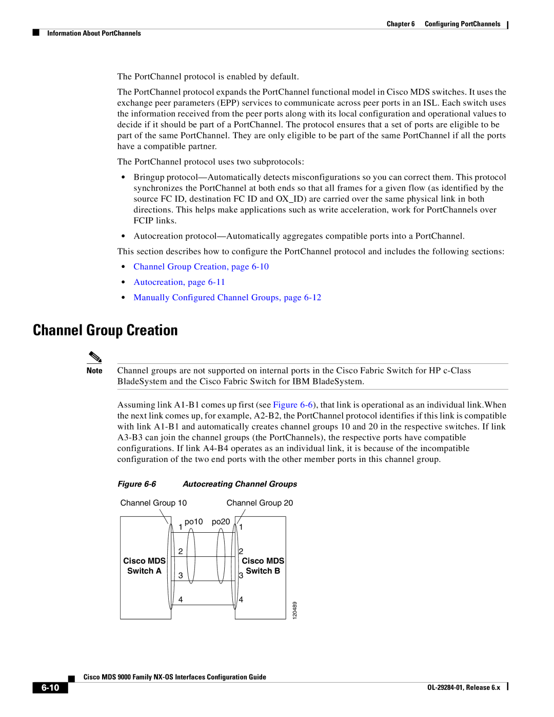
Autocreating Channel Groups
User-Configured Channel Group Autocreated Channel Group
Autocreation
Manually Configured Channel Groups
Prerequisites for PortChannels
Configuring PortChannels Guidelines and Limitations
Generation 1 PortChannel Limitations
TF PortChannel Limitations
7provides examples of valid PortChannel configurations
Valid and Invalid PortChannel Examples
3lists the default settings for PortChannels
Misconfigured Configurations
Default PortChannel Parameters
Configuring PortChannels
Configuring the PortChannel Mode
Configures the specified PortChannel 1 using
Default on mode
Deleting PortChannels
Adding an Interface to a PortChannel
Forcing an Interface Addition
Deleting an Interface from a PortChannel
Verifying PortChannel Configuration
Enabling and Configuring Autocreation
Converting to Manually Configured Channel Groups
Switch# show port-channel summary
Switch# show port-channel database port-channel
Example 6-1 Displays the PortChannel Summary
Port-channel database
Switch# show port-channel consistency
Switch# show port-channel consistency detail
Example 6-4 Displays the Consistency Status without Details
Example 6-5 Displays the Consistency Status with Details
Example 6-6 Displays the PortChannel Usage
Example 6-7 Displays the PortChannel Compatibility
Example 6-8 Displays Autocreated PortChannels
Example 6-9 Displays the Specified PortChannel Interface
Configuration Examples for F and TF PortChannels
Create the PortChannel on the MDS core switch
Create the PortChannel on the NPV switch
Example 6-10 Displays the PortChannel Summary
Create the PortChannel in dedicated mode on the NPV switch
Switchconfig# interface port-channel
Cisco MDS 9000 Family NX-OS Interfaces Configuration Guide
Configuring N Port Virtualization
NPV Overview
Port Identifier Virtualization
Port Virtualization
Npiv Example
Cisco NPV Fabric Configuration
NPV Mode
NP Ports
NP Links
Internal Flogi Parameters
Default Port Numbers
Parameter Derived From
Internal Flogi Parameters
NPV CFS Distribution over IP
NPV Traffic Management
Auto
Traffic Map
Multiple Vsan Support
Disruptive
NPV Guidelines and Requirements
Dpvm Configuration Guidelines
NPV Traffic Management Guidelines
Configuring N Port Virtualization
Configuring NPV
NPV and Port Security Configuration Guidelines
Enabling N Port Identifier Virtualization
To configure NPV using the CLI, perform the following tasks
On the NPV core switch, enters configuration
Enables Npiv mode on the NPV core switch
Disables Npiv mode on the NPV core switch
Configuring NPV Traffic Management
Verifying NPV Configuration
Enabling the Global Policy for Disruptive Load Balancing
Switch# show fcns database
Switch# show fcns database detail
Verifying NPV
Switch# show npv flogi-table
Switch# show npv internal info traffic-map
Verifying NPV Traffic Management
OL-29284-01, Release
Information About FlexAttach Virtual pWWN
FlexAttach Virtual pWWN
FlexAttach Virtual pWWN CFS Distribution
SAN Device Virtualization SDV FlexAttach Virtualization
Difference Between SDV and FlexAttach Virtualization
Configuring FlexAttach Virtual pWWN
Security Settings for FlexAttach Virtual pWWN
Automatically Assigning FlexAttach Virtual pWWN
Manually Assigning FlexAttach Virtual pWWN
Mapping pWWN to Virtual pWWN
Verifying FlexAttach Virtual pWWN Configuration
Commits the configuration
Specified virtual pWWN and the real pWWN must not be logged
To map pWWN to virtual pWWN, perform this task
Error Description Workaround
Monitoring FlexAttach Virtual pWWN
Verifying the End Device
Error Description Workaround
OL-29284-01, Release
Configuring Port Tracking
Information About Port Tracking
1lists the default settings for port tracking parameters
Default Port Tracking Parameters
Configuring Port Tracking
Information About Configuring Linked Ports
Enabling Port Tracking
Binding a Tracked Port Operationally
Information About Tracking Multiple Ports
Tracking Multiple Ports
Information About Monitoring Ports in a Vsan
Monitoring Ports in a Vsan
Displaying Port Tracking Information
Information AboutForceful Shutdown
Forcefully Shutting Down a Tracked Port
Linked port
Switch# show interface fc1/1
Switch# show interface port-channel
Port linked to interface fc1/1
Example 9-4 Displays a Forced Shutdown Configuration
Switch# show interface fc 1/5
Bandwidth fairness Default settings Example configurations
Port 10-Gbps switching modules
Asterisk First operational port
IN-2
Deleting from PortChannels
IN-3
Configuring descriptions
MPS-14/2 modules Configuring extended BBcredits
IN-5
IN-6
TL ports Alpa caches Configuring
Trunk mode Administrative default Configuring
Status Trunk ports Displaying information
IN-8