IPS4520K9, IPS4510K9 specifications
Cisco Systems has long been a leading player in network security, and its IPS (Intrusion Prevention System) series is a testament to its commitment to safeguarding digital environments. Among its notable offerings are the IPS4510K9 and IPS4520K9 models, both designed to provide advanced threat protection for mid-sized to large enterprise networks.The Cisco IPS4510K9 and IPS4520K9 are distinguished by their cutting-edge features that help organizations defend against a myriad of cyber threats. These systems utilize a multi-layered approach to security, integrating intrusion prevention, advanced malware protection, and comprehensive visibility across the network.
One of the primary characteristics of the IPS4510K9 is its high performance. It boasts a throughput of up to 1 Gbps, making it suitable for environments that demand rapid data processing and real-time responses to threats. The IPS4520K9, on the other hand, enhances that capability with improved throughput of up to 2 Gbps, accommodating larger enterprises with heavier network traffic. These models are equipped with powerful processors that support complex signature matching and can intelligently distinguish between legitimate traffic and potential threats.
In addition to performance, both models are designed with scalability in mind. They can be easily integrated into existing Cisco infrastructures. This facilitates a seamless enhancement of security without causing significant interruptions to ongoing operations. Moreover, they offer flexible deployment options, allowing organizations to operate them inline or out of band depending on their specific needs.
The Cisco IPS4510K9 and IPS4520K9 leverage advanced detection technologies, utilizing a variety of signature types and heuristic analysis to detect known and unknown threats effectively. They are equipped with real-time alerting and reporting capabilities, giving security teams immediate visibility into potential breaches and enabling them to respond swiftly.
Furthermore, both models support a range of management options through the Cisco Security Manager, allowing for centralized administration, streamlined policy management, and enhanced monitoring capabilities. Automated updates ensure the systems remain current with the latest threat intelligence, vital for staying ahead of evolving cyber threats.
In summary, the Cisco Systems IPS4510K9 and IPS4520K9 represent powerful solutions for organizations seeking robust intrusion prevention capabilities. With their high performance, scalability, and advanced detection technologies, these systems are essential tools in the ever-changing landscape of cybersecurity, providing enterprises with the peace of mind needed to operate securely in today's digital world.

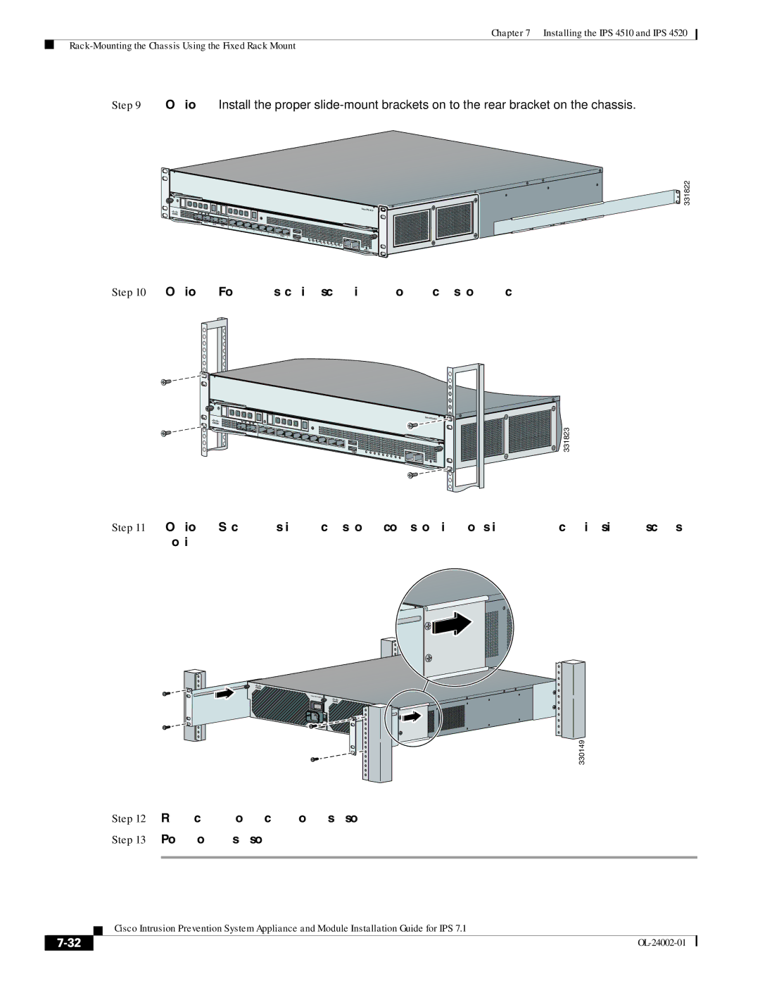
 331823