Cisco Systems MWR 1900 manual Connecting the VWIC Interface Cables

Models: MWR 1900

1 48
Download 48 pages 558 b
Page 27
Image 27
Connecting the VWIC Interface Cables

Chapter 3 Installing the Router

Connecting the Network Cables

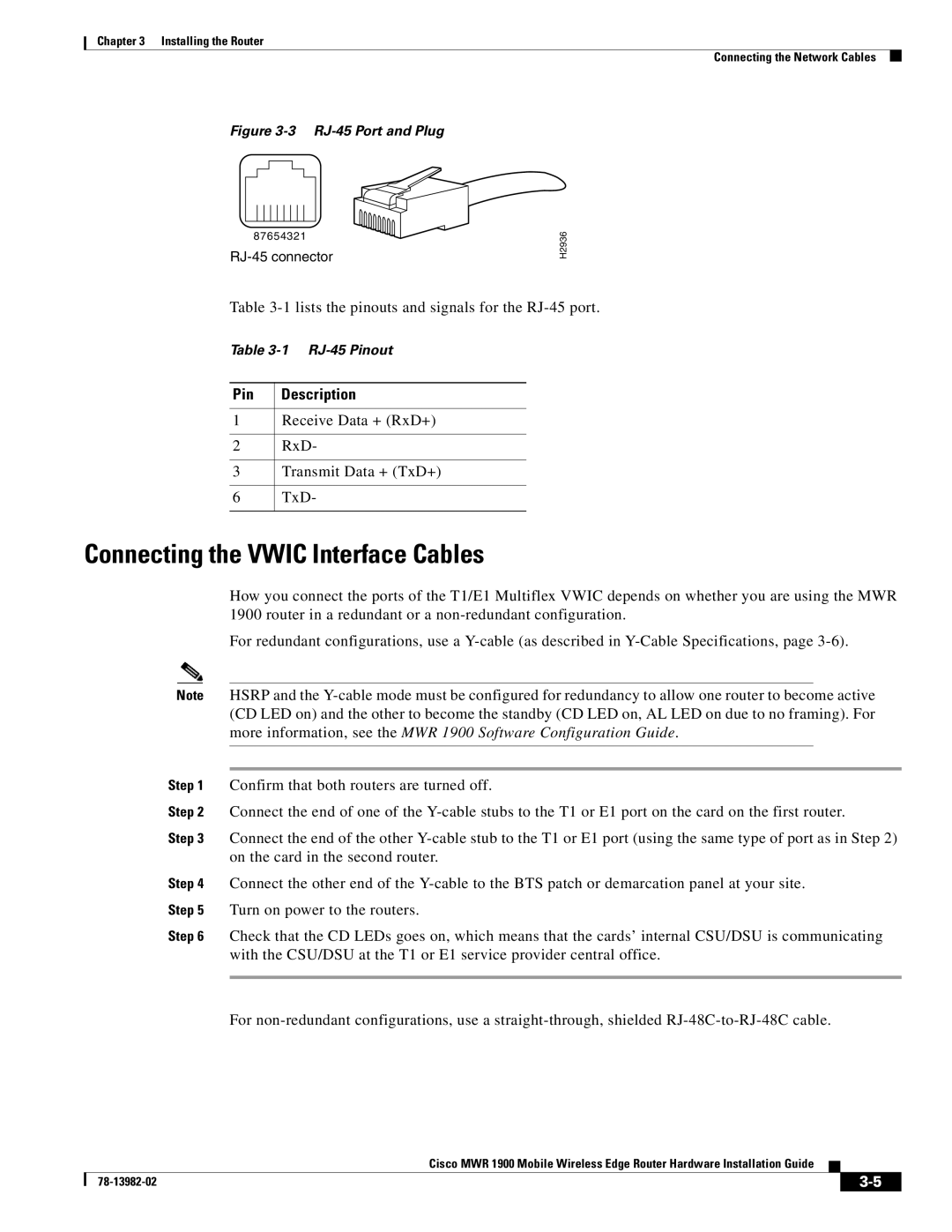
Figure 3-3 RJ-45 Port and Plug

87654321

RJ-45 connector

H2936

Table 3-1lists the pinouts and signals for the RJ-45 port.

Table 3-1 RJ-45 Pinout

Pin

Description


1

Receive Data + (RxD+)


2

RxD-


3

Transmit Data + (TxD+)


6

TxD-


Connecting the VWIC Interface Cables

How you connect the ports of the T1/E1 Multiflex VWIC depends on whether you are using the MWR 1900 router in a redundant or a non-redundant configuration.

For redundant configurations, use a Y-cable (as described in Y-Cable Specifications, page 3-6).

Note HSRP and the Y-cable mode must be configured for redundancy to allow one router to become active (CD LED on) and the other to become the standby (CD LED on, AL LED on due to no framing). For more information, see the MWR 1900 Software Configuration Guide.

Step 1 Confirm that both routers are turned off.

Step 2 Connect the end of one of the Y-cable stubs to the T1 or E1 port on the card on the first router.

Step 3 Connect the end of the other Y-cable stub to the T1 or E1 port (using the same type of port as in Step 2) on the card in the second router.

Step 4 Connect the other end of the Y-cable to the BTS patch or demarcation panel at your site. Step 5 Turn on power to the routers.

Step 6 Check that the CD LEDs goes on, which means that the cards’ internal CSU/DSU is communicating with the CSU/DSU at the T1 or E1 service provider central office.

For non-redundant configurations, use a straight-through, shielded RJ-48C-to-RJ-48C cable.

Cisco MWR 1900 Mobile Wireless Edge Router Hardware Installation Guide


78-13982-02

3-5


Page 27
Image 27
Cisco Systems MWR 1900 manual Connecting the VWIC Interface Cables