Chapter 1 Overview of the Cisco MWR 1900 Router
Hardware Features
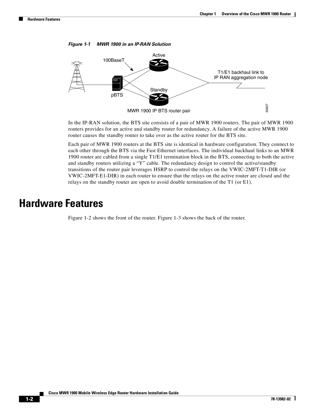
Figure 1-1 MWR 1900 in an IP-RAN Solution
Active
100BaseT
![]() Standby pBTS
Standby pBTS![]()
MWR 1900 IP BTS router pair
T1/E1 backhaul link to
IP RAN aggregation node
65827
In the
Each pair of MWR 1900 routers at the BTS site is identical in hardware configuration. They connect to each other through the BTS via the Fast Ethernet interfaces. The individual backhaul links to an MWR 1900 router are cabled from a single T1/E1 termination block in the BTS, connecting to both the active and standby routers utilizing a “Y” cable. The redundancy design to control the active/standby transitions of the router pair leverages HSRP to control the relays on the
Hardware Features
Figure 1-2 shows the front of the router. Figure 1-3 shows the back of the router.
Cisco MWR 1900 Mobile Wireless Edge Router Hardware Installation Guide
| ||
|