Chapter 3 Express Setup
Express Setup
Step 2 Verify that no device is connected to the switch module.
Step 3 Temporarily configure your computer to use DHCP, if it has a static IP address. The switch module acts as a DHCP server.
Tip Write down the static IP address, as you need this address in a later step.
Step 4 Power on the CGR 2010 router. Once the host router is powered up, the router automatically powers up the switch model.
For more information, see “Powering Up the Router” in Chapter 4, “Configuring the Router,” in the Cisco Connected Grid Routers 2010 Hardware Installation Guide.
Once the switch module powers on, it starts the
•During POST, the System LED blinks green and then port LEDs turn green
•When POST is complete, the System LED remains green and the other LEDs turn off
Note If the System LED blinks green, does not turn green or turns amber, the switch module failed POST. Contact your Cisco representative or reseller.
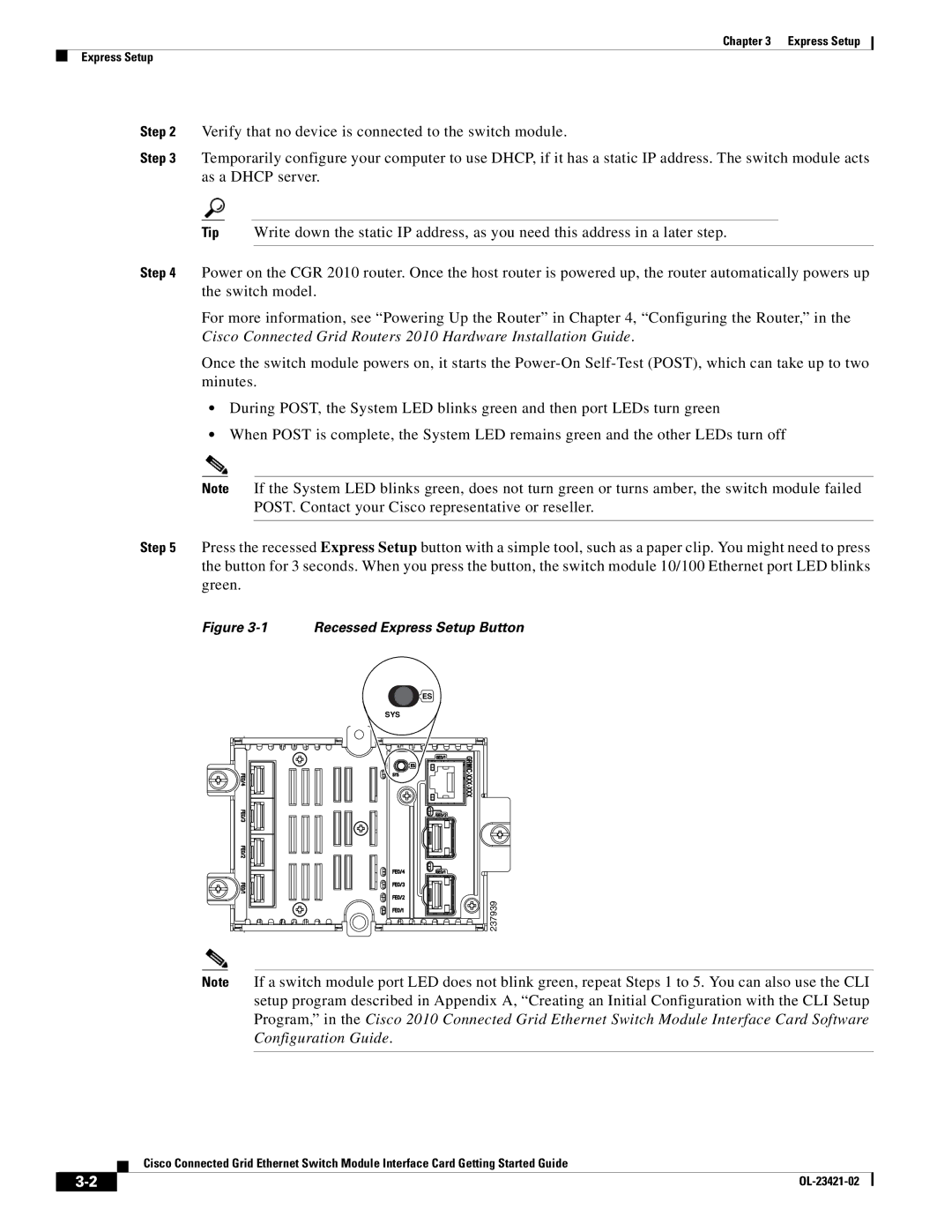
Step 5 Press the recessed Express Setup button with a simple tool, such as a paper clip. You might need to press the button for 3 seconds. When you press the button, the switch module 10/100 Ethernet port LED blinks green.
Figure 3-1 Recessed Express Setup Button
ES |
SYS |
237939 |
Note If a switch module port LED does not blink green, repeat Steps 1 to 5. You can also use the CLI setup program described in Appendix A, “Creating an Initial Configuration with the CLI Setup Program,” in the Cisco 2010 Connected Grid Ethernet Switch Module Interface Card Software Configuration Guide.
Cisco Connected Grid Ethernet Switch Module Interface Card Getting Started Guide
|
| |
|