Appendix A Cable and Connectors
Cables and Adapters
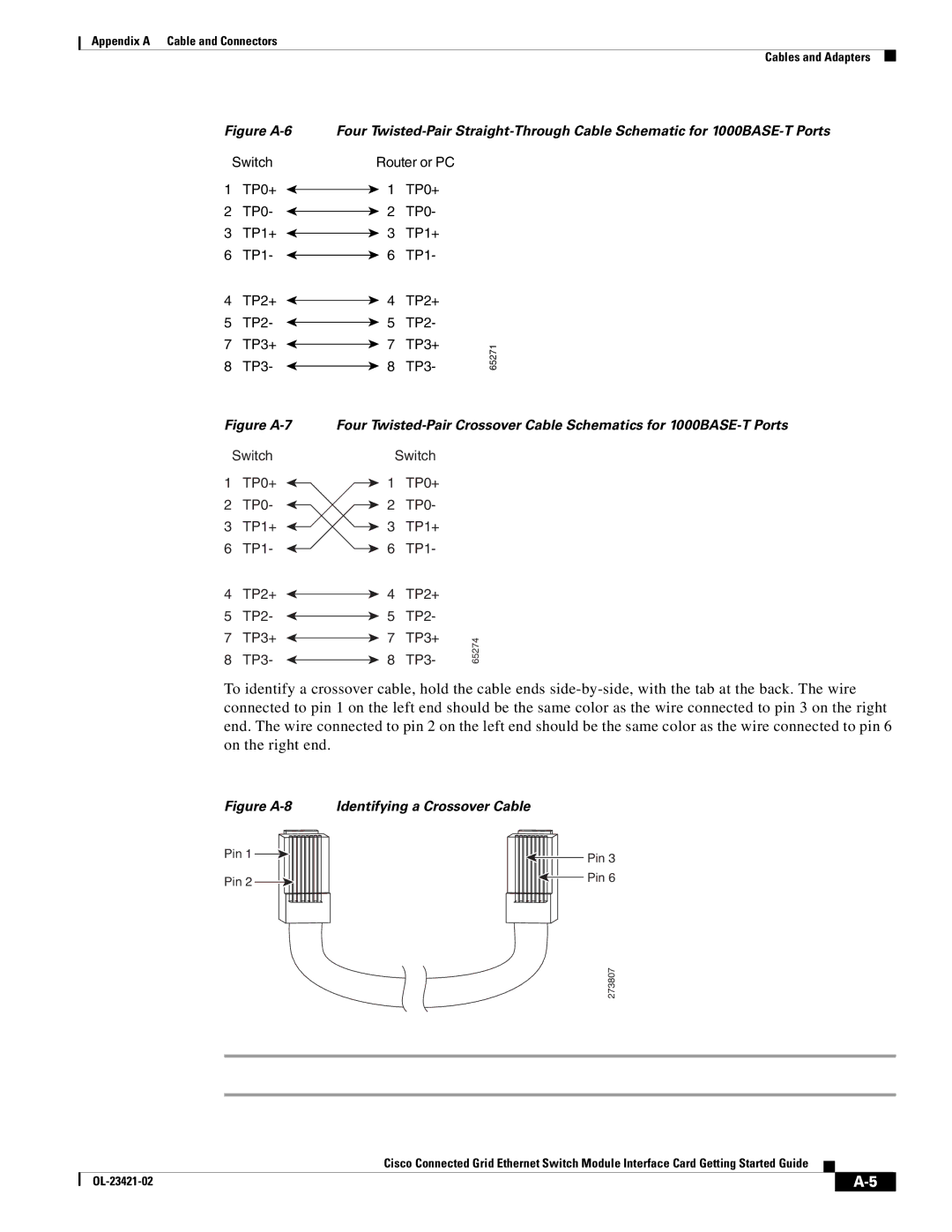
Figure A-6
Switch
1 TP0+
2 TP0-
3 TP1+
6 TP1-
4 TP2+
5 TP2-
7 TP3+
8 TP3-
Figure A-7
Switch
1 TP0+
2 TP0-
3 TP1+
6 TP1-
4 TP2+
5 TP2-
7 TP3+
8 TP3-
Four
Router or PC
1 TP0+
2 TP0-
3 TP1+
6 TP1-
4 | TP2+ |
| |
5 | TP2- |
| |
7 | TP3+ | 65271 | |
8 | TP3- | ||
|
Four
| Switch |
| |
1 | TP0+ |
| |
2 | TP0- |
| |
3 | TP1+ |
| |
6 | TP1- |
| |
4 | TP2+ |
| |
5 | TP2- |
| |
7 | TP3+ | 65274 | |
8 | TP3- | ||
|
To identify a crossover cable, hold the cable ends
Figure A-8 Identifying a Crossover Cable
Pin 1 |
|
|
|
|
|
|
|
|
| Pin 3 |
|
|
|
|
|
|
| ||||
|
|
|
|
|
|
|
|
| ||
|
|
|
|
|
|
|
|
|
| |
Pin 2 |
|
|
|
|
|
|
|
|
| Pin 6 |
|
|
|
|
|
|
|
|
| ||
|
|
|
|
|
|
|
|
| ||
|
|
|
|
|
|
|
|
|
|
|
|
|
|
|
|
|
|
|
|
|
|
273807
Cisco Connected Grid Ethernet Switch Module Interface Card Getting Started Guide
| ||
|