Chapter 1 Product Overview
LEDs
LEDs
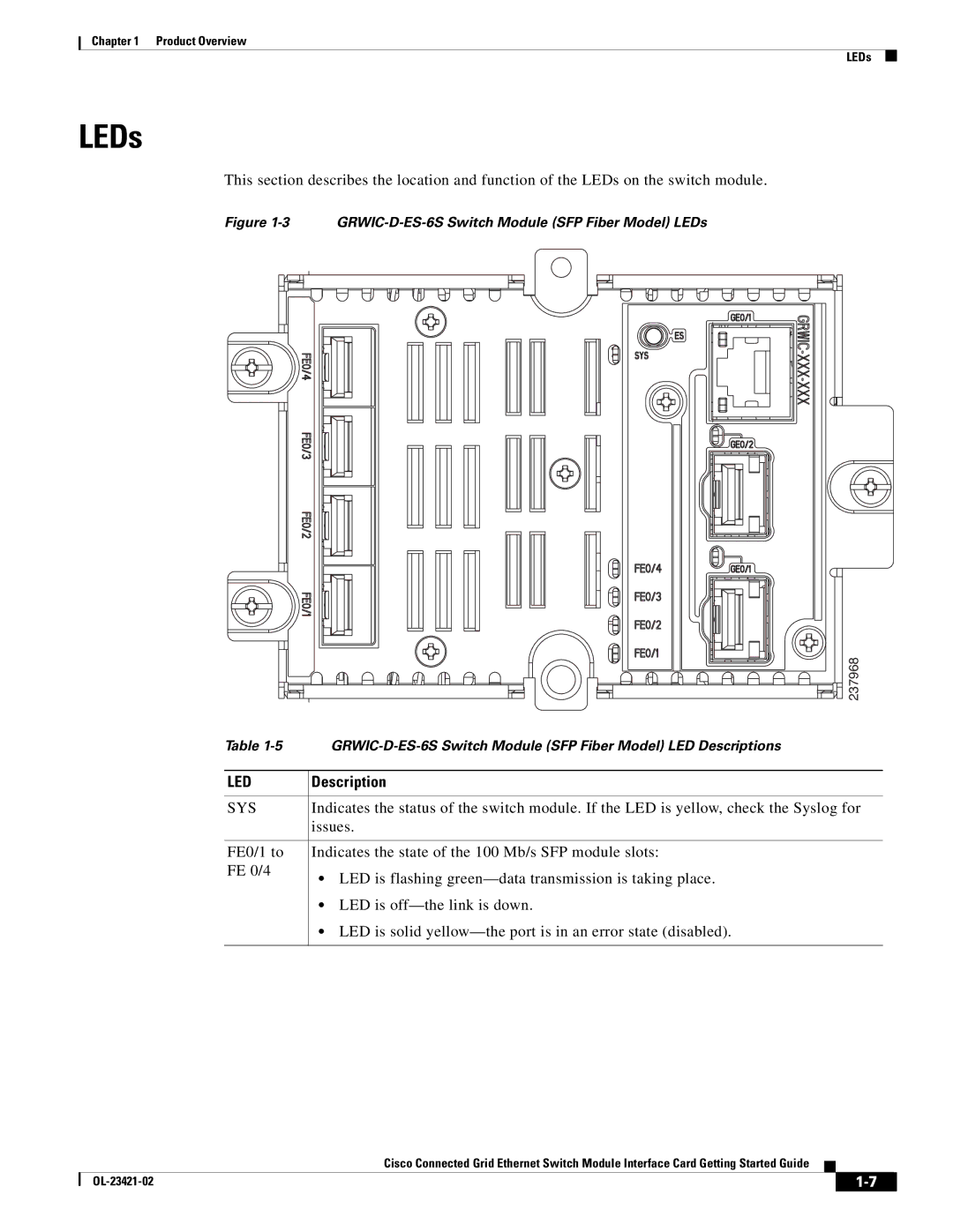
This section describes the location and function of the LEDs on the switch module.
Figure 1-3 GRWIC-D-ES-6S Switch Module (SFP Fiber Model) LEDs
| 237968 |
Table | |
LED | Description |
SYS | Indicates the status of the switch module. If the LED is yellow, check the Syslog for |
| issues. |
FE0/1 to | Indicates the state of the 100 Mb/s SFP module slots: |
FE 0/4 | • LED is flashing |
|
•LED is
•LED is solid
Cisco Connected Grid Ethernet Switch Module Interface Card Getting Started Guide
|
| ||
|
|