Text Part Number OL-23421-02
Cisco Systems, Inc
Cisco Connected Grid Ethernet Switch
Module Interface Card Getting Started Guide
2012-2014 Cisco Systems, Inc. All rights reserved
No combinations are authorized or intended under this document
Switch Models
Obtaining Documentation and Submitting a Service Request
Installation
Pre-Installation
SFP Module Connectors
Cisco Configuration Professional
Resetting the Switch Module
Managing the Switch Module
Purpose
Preface
Document Conventions
Obtaining Documentation and Submitting a Service Request
Related Publications
C H A P T E R
Switch Models
Switch Models, page Ports, page LEDs, page
Product Overview
PoE and PoE+ Ports, page 10/100 Mb/s SFP Module Slots, page
Ports
Port Locations
Port Locations, page Port Labeling, page 10/100BASE-T Ports, page
Port
Port Labeling
Label
PoE and PoE+ Ports
10/100BASE-T Ports
GRWIC-D-ES-2S-8PC Port Labeling
100/1000 Mb/s SFP Module Slots
10/100 Mb/s SFP Module Slots
Dual-Purpose Gigabit Ethernet Ports
Type of SFP Module
Supported SFPs
Model
LEDs
Description
GRWIC-D-ES-2S-8PC Switch Module Copper Model LEDs
Description
Router Compact Flash Memory Cards
flash0
1-10
flash1
flash or
Pre-Installation Installation Connecting to the Network
Installation
Pre-Installation
Installation Warning Statements
Installation
OL-23421-02
Figure 2-2 Positioning the Switch Module to Install in the Router
Chapter 2 Installation Installation
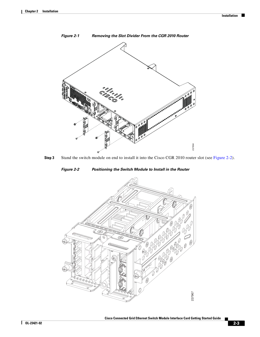
Figure 2-1 Removing the Slot Divider From the CGR 2010 Router
Step 5 Tighten the screws
Connecting the Fiber Switch Module, page
Connecting to the Network
Connecting the Copper Switch Module
Connecting the Copper Switch Module, page
Figure 2-5 Connecting the Copper Model to the Network
Connecting the Fiber Switch Module
Removing the Switch Module
OL-23421-02
Chapter 2 Installation Removing the Switch Module
Resetting the Switch Module
Express Setup
Express Setup
System Requirements Express Setup Troubleshooting Express Setup
Step 2 Verify that no device is connected to the switch module
Step 6 Select one of the following
Step 3 Enter the Network Settings values
Resolution
Troubleshooting Express Setup
Resetting the Switch Module
Problem
Chapter 3 Express Setup Resetting the Switch Module
Step 3 Follow the steps in Express Setup, page
OL-23421-02
Using the Device Manager Cisco Configuration Professional
Managing the Switch Module
Using the Device Manager
Cisco Configuration Professional
IP Address
Accessing the Switch Module
Other Management Options
Interface
Disconnecting from the Switch Module
Dual-Purpose Port with RJ-45 and SFP Connectors, page
Connecting Devices to the Switch Module
Dual-Purpose Port with RJ-45 and SFP Connectors, page
10/100BASE-T Ports, page SFP Module Slots, page
237940
SFP Module Slots
Chapter 4 Managing the Switch Module
237941
237942
Figure 4-3 Connecting the Cable into the SFP Port
Dual-Purpose Port with RJ-45 and SFP Connectors
Figure 4-4 Ethernet Cable Connected to the RJ-45 Connector
237964
Figure 4-5 Dual-Purpose Connectors
Verifying Port Connectivity
237965
OL-23421-02
4-10
Chapter 4 Managing the Switch Module
Connecting Devices to the Switch Module
Connector Specifications, page A-1 Cables and Adapters, page A-2
Cable and Connectors
Connector Specifications
SFP Module Connectors
SFP Module Cables, page A-2 Cable Pinouts, page A-4
Cables and Adapters
Dual-Purpose Ports
SFP Module Cables
Size/Cladding
Cable Pinouts
Figure A-8 Identifying a Crossover Cable
Four Twisted-Pair Crossover Cable Schematics for 1000BASE-T Ports
Figure A-6
Figure A-7
OL-23421-02
Appendix A Cable and Connectors Cables and Adapters