Chapter 4 Troubleshooting the System
Troubleshooting Using Cable Flap Lists
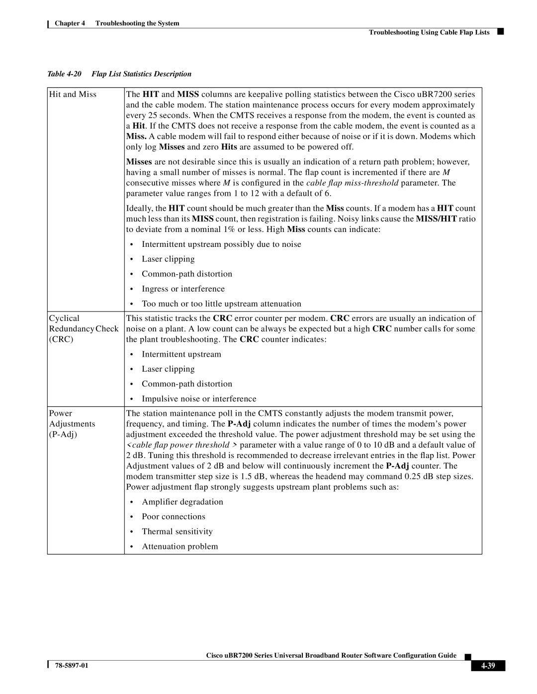
Table
Hit and Miss | The HIT and MISS columns are keepalive polling statistics between the Cisco uBR7200 series | |
| and the cable modem. The station maintenance process occurs for every modem approximately | |
| every 25 seconds. When the CMTS receives a response from the modem, the event is counted as | |
| a Hit. If the CMTS does not receive a response from the cable modem, the event is counted as a | |
| Miss. A cable modem will fail to respond either because of noise or if it is down. Modems which | |
| only log Misses and zero Hits are assumed to be powered off. | |
| Misses are not desirable since this is usually an indication of a return path problem; however, | |
| having a small number of misses is normal. The flap count is incremented if there are M | |
| consecutive misses where M is configured in the cable flap | |
| parameter value ranges from 1 to 12 with a default of 6. | |
| Ideally, the HIT count should be much greater than the Miss counts. If a modem has a HIT count | |
| much less than its MISS count, then registration is failing. Noisy links cause the MISS/HIT ratio | |
| to deviate from a nominal 1% or less. High Miss counts can indicate: | |
| • Intermittent upstream possibly due to noise | |
| • | Laser clipping |
| • | |
| • | Ingress or interference |
| • Too much or too little upstream attenuation | |
|
| |
Cyclical | This statistic tracks the CRC error counter per modem. CRC errors are usually an indication of | |
Redundancy Check | noise on a plant. A low count can be always be expected but a high CRC number calls for some | |
(CRC) | the plant troubleshooting. The CRC counter indicates: | |
| • | Intermittent upstream |
| • | Laser clipping |
| • | |
| • Impulsive noise or interference | |
|
| |
Power | The station maintenance poll in the CMTS constantly adjusts the modem transmit power, | |
Adjustments | frequency, and timing. The | |
adjustment exceeded the threshold value. The power adjustment threshold may be set using the | ||
| <cable flap power threshold > parameter with a value range of 0 to 10 dB and a default value of | |
| 2 dB. Tuning this threshold is recommended to decrease irrelevant entries in the flap list. Power | |
| Adjustment values of 2 dB and below will continuously increment the | |
| modem transmitter step size is 1.5 dB, whereas the headend may command 0.25 dB step sizes. | |
| Power adjustment flap strongly suggests upstream plant problems such as: | |
| • | Amplifier degradation |
| • | Poor connections |
| • | Thermal sensitivity |
| • | Attenuation problem |
|
|
|
Cisco uBR7200 Series Universal Broadband Router Software Configuration Guide
|
| ||
|
|