Chapter
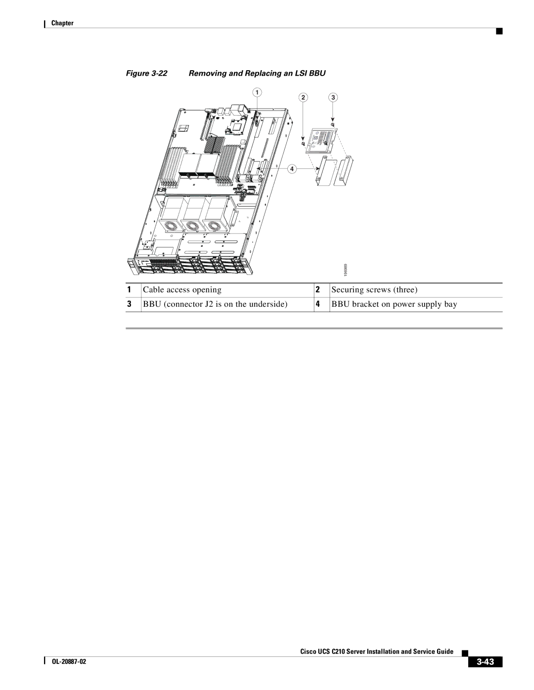
Figure 3-22 Removing and Replacing an LSI BBU
1
2 3
4
|
|
| 196989 |
1 | Cable access opening | 2 | Securing screws (three) |
3 | BBU (connector J2 is on the underside) | 4 | BBU bracket on power supply bay |
|
| Cisco UCS C210 Server Installation and Service Guide |
|
| |
|
|
| |||
|
|
|
| ||
|
|
|
| ||
