ENGLISH
4.SETTING DIP SWITCHES
4.1Location of DIP Switches
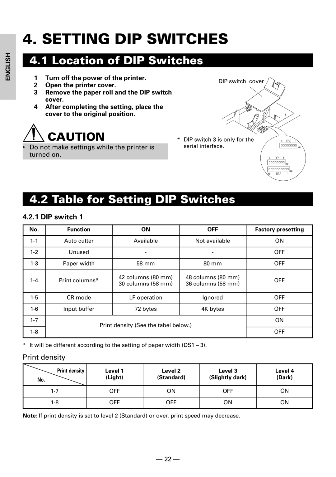
1Turn off the power of the printer.
2Open the printer cover.
3Remove the paper roll and the DIP switch cover.
4After completing the setting, place the cover to the original position.
![]() CAUTION
CAUTION
•Do not make settings while the printer is turned on.
DIP switch cover
*DIP switch 3 is only for the serial interface.
4.2Table for Setting DIP Switches
4.2.1DIP switch 1
No. | Function |
| ON | OFF | Factory presetting |
|
|
|
|
|
|
Auto cutter |
| Available | Not available | ON | |
|
|
|
|
|
|
Unused |
| - | - | OFF | |
|
|
|
|
|
|
Paper width |
| 58 mm | 80 mm | OFF | |
|
|
|
|
|
|
Print columns* |
| 42 columns (80 mm) | 48 columns (80 mm) | OFF | |
| 30 columns (58 mm) | 36 columns (58 mm) | |||
|
|
|
| ||
|
|
|
|
|
|
CR mode |
| LF operation | Ignored | OFF | |
|
|
|
|
|
|
Input buffer |
| 72 bytes | 4K bytes | OFF | |
|
|
|
|
|
|
| Print density (See the tabel below.) | ON | |||
|
|
| |||
| OFF | ||||
|
|
|
| ||
|
|
|
|
|
|
* It will be different according to the setting of paper width (DS1 – 3).
Print density
Print density | Level 1 | Level 2 | Level 3 | Level 4 |
No. | (Light) | (Standard) | (Slightly dark) | (Dark) |
|
|
|
| |
|
|
|
|
|
OFF | ON | OFF | ON | |
|
|
|
|
|
OFF | OFF | ON | ON | |
|
|
|
|
|
Note: If print density is set to level 2 (Standard) or over, print speed may decrease.
— 22 —