APPENDIX 5. SERIAL INTERFACE
1 Specifications |
| |
(1) | Synchronizing system: | Asynchronous |
(2) | Baud rate : | 4800, 9600, 19200 or 38400 bps (User selectable) |
(3) | Configuration of one word |
|
| Start bit: | 1 bit |
| Data bits: | 7 or 8 bits (User selectable) |
| Parity bit: | Odd, even, or none (User selectable) |
| Stop bit: | 1 bit or more |
| Transmission control: | DTR/DSR or XON/XOFF control (User selectable) |
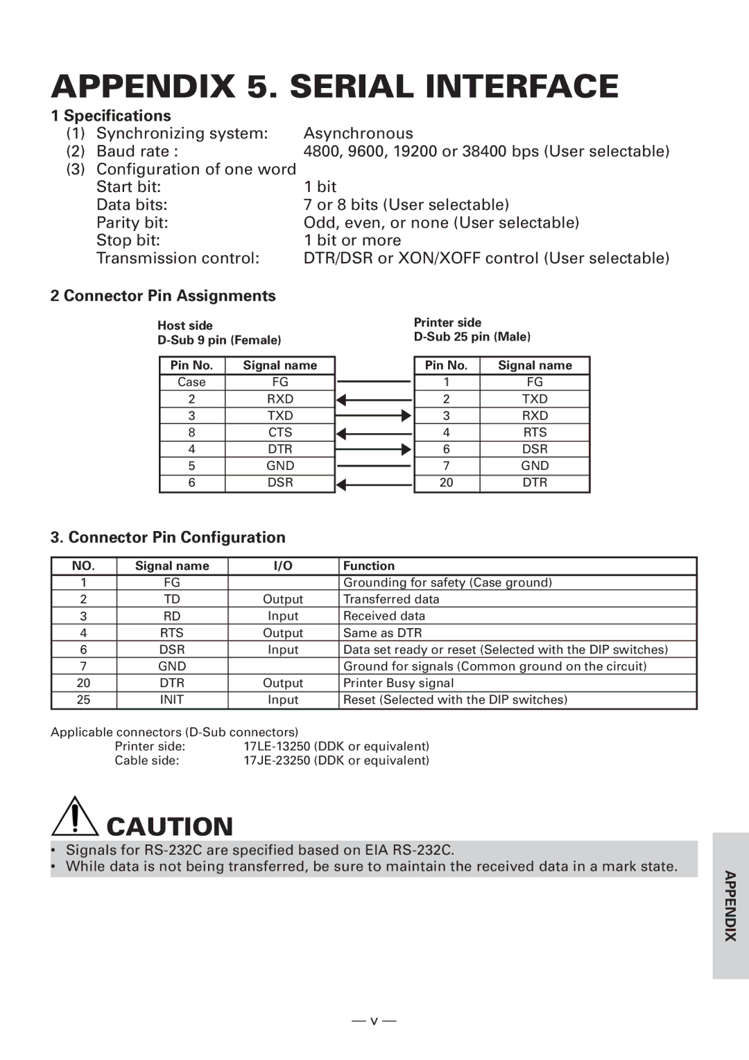
2 Connector Pin Assignments
Host side
Pin No. | Signal name |
|
|
Case | FG |
|
|
|
| ||
2 | RXD |
|
|
|
| ||
3 | TXD |
|
|
|
| ||
8 | CTS |
|
|
|
| ||
4 | DTR |
|
|
|
| ||
5 | GND |
|
|
|
| ||
6 | DSR |
|
|
|
|
Printer side
Pin No. | Signal name |
1 | FG |
2 | TXD |
3 | RXD |
4 | RTS |
6 | DSR |
7 | GND |
20 | DTR |
3. Connector Pin Configuration
NO. | Signal name | I/O | Function |
1 | FG |
| Grounding for safety (Case ground) |
2 | TD | Output | Transferred data |
3 | RD | Input | Received data |
4 | RTS | Output | Same as DTR |
6 | DSR | Input | Data set ready or reset (Selected with the DIP switches) |
7 | GND |
| Ground for signals (Common ground on the circuit) |
20 | DTR | Output | Printer Busy signal |
25 | INIT | Input | Reset (Selected with the DIP switches) |
Applicable connectors |
| ||
| Printer side: | ||
| Cable side: | ||
| CAUTION |
| |
|
| ||
• | Signals for |
|
|
• | While data is not being transferred, be sure to maintain the received data in a mark state. |
| APPENDIX |
|
|
| |
|
|
|
|
— v —