3.3 Connecting the Drawer Kick-Out Connector
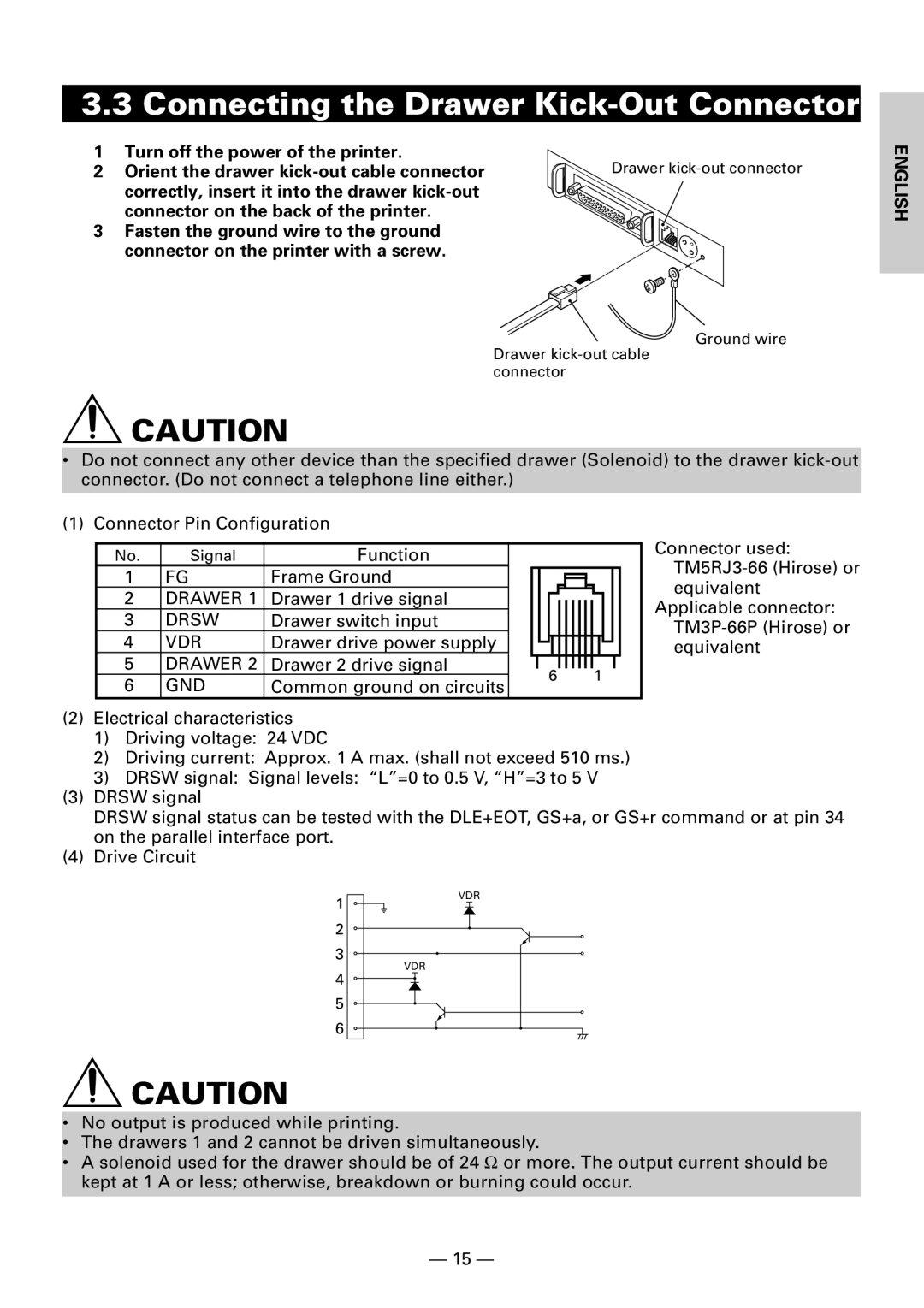
1 | Turn off the power of the printer. | Drawer |
2 | Orient the drawer | |
| correctly, insert it into the drawer |
|
| connector on the back of the printer. |
|
3 | Fasten the ground wire to the ground |
|
| connector on the printer with a screw. |
|
ENGLISH
Ground wire
Drawer
![]() CAUTION
CAUTION
•Do not connect any other device than the specified drawer (Solenoid) to the drawer
(1) Connector Pin Configuration
No. | Signal | Function |
1 | FG | Frame Ground |
2DRAWER 1 Drawer 1 drive signal
3DRSW Drawer switch input
4 | VDR | Drawer drive power supply |
|
|
|
|
|
|
|
|
|
|
|
|
|
|
|
|
| ||||
5 | DRAWER 2 | Drawer 2 drive signal |
|
|
|
|
|
|
|
|
|
|
|
|
|
|
|
|
| ||||
6 | 1 |
|
| ||||||||
6 | GND | Common ground on circuits |
|
| |||||||
|
|
|
|
|
|
|
| ||||
Connector used:
Applicable connector:
(2)Electrical characteristics
1)Driving voltage: 24 VDC
2)Driving current: Approx. 1 A max. (shall not exceed 510 ms.)
3)DRSW signal: Signal levels: “L”=0 to 0.5 V, “H”=3 to 5 V
(3)DRSW signal
DRSW signal status can be tested with the DLE+EOT, GS+a, or GS+r command or at pin 34 on the parallel interface port.
(4)Drive Circuit
1
2
3
4
5
6
![]() CAUTION
CAUTION
VDR
VDR
•No output is produced while printing.
•The drawers 1 and 2 cannot be driven simultaneously.
•A solenoid used for the drawer should be of 24 Ω or more. The output current should be kept at 1 A or less; otherwise, breakdown or burning could occur.
— 15 —