Chapter 8 Maintenance
DTR protocol
DTR signal “Ready (High)” level requirements:
The following must be satisfied:
·Printer is on line.
·Receive buffer has more than 128 bytes available.
Note: When receive buffer has less than 128 bytes available, DTR signal becomes “Busy (Low)” level and this “Busy (Low) level is kept until receive buffer has at least 1K bytes available.
DTR signal “Busy (Low)” level requirements:
The following must be satisfied:
·Printer is in error.
·Printer is in paused state.
·Receive buffer has less than 128 bytes available.
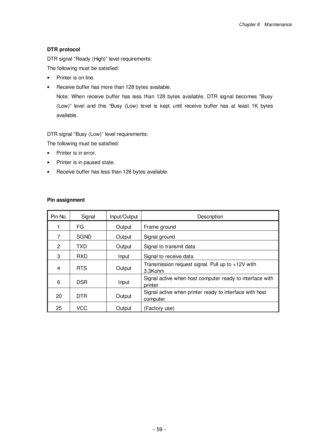
Pin assignment
Pin No. | Signal | Input/Output | Description | |
1 | FG | Output | Frame ground | |
7 | SGND | Output | Signal ground | |
2 | TXD | Output | Signal to transmit data | |
3 | RXD | Input | Signal to receive data | |
4 | RTS | Output | Transmission request signal. Pull up to +12V with | |
3.3Kohm | ||||
|
|
| ||
6 | DSR | Input | Signal active when host computer ready to interface with | |
printer | ||||
|
|
| ||
20 | DTR | Output | Signal active when printer ready to interface with host | |
computer | ||||
|
|
| ||
25 | VCC | Output | (Factory use) |
- 59 -
