Line Thermal Printer
Weee Mark
Declaration of Conformity
Important Safety Instructions
Wichtige Sicherheitsanweisungen
Lärmemission kleiner 70dBA
Sicherheitshinweis
General Precautions
Safety Precautions Which should be Strictly Observed
Page
Precautions for Installation
Precautions for Handling
To prevent injuries and associated damages
HOT Area
Daily Maintenance
Cleaning the print head
Table of Contents
Maintenance and Service
152
141
158
167
166
169
Inhalt
179
194
198
208
203
210
Features
General Outline
Unpacking
Before using the printer
Basic Specifications
Model Classification
Basic Specifications
Code 39, Code 128, CODABAR, Code
Print Paper Specifications
Recommended Paper
Print Position and Barcode Printing
Roll paper width 112 mm provided
Cutter Position
Outer Appearance and Component Parts
IDP3240
Connecting the AC Adapter and AC Power Cord
Operation
Connecting Interface Cables
Connecting the Drawer Kick-Out Connector
Turn off the power of the printer
Setting Paper Rolls
Setting / Replacing Paper Rolls
Good No Good
Cover, and close the printer cover
Page
Top cover
Removing the Remainder of Paper Rolls
Open the printer cover
Removing Paper Jams
Releasing a Locked Cutter
Cleaning the Print Head
Remove the platen roller unit Following the procedure
Operation Panel and Error Indication
Power lamp Green
Error lamp Red
Error indication
Feed switch
Print Control Functions
Self Printing
Performing Self Printing
Hexadecimal Dump
Starting hexadecimal dump
Setting DIP Switches
Location of DIP Switches
DIP switch
Table for Setting DIP Switches
Print density DIP switch
Selection of Character Code tables DIP switch
Baud rate DIP switch
Reverse Mode Printer → Host communication
Parallel Interface
Bidirectional Parallel Interface IEEE1284
Outline
Connector Pin Configuration
Dkstatus
Description of Input and Output Signals
Input and Output Signals
Input signals to the printer
Output signals from the printer
Electrical Characteristics
Input signal level nStrobe, Data
Output signal level
Input and output conditions
Timing Chart Compatibility Mode
Data Reception Control
Buffering
Data input and print timing
Specifications
Serial Interface
Connector Pin Configuration
DTR, RTS
DSR
Init
GND
Error Detection
Framing error
Parity error
Overrun error
RS-232C circuit
Specifications of Drawer Kick-Out Connector
Drawer Kick-Out drive signal
Pin configuration of Power connector
Specifications of the Power Connector
Drive Circuit
Maintenance and Service
Function Mode Code
Command List
Print Control Functions
ESC T
Command relative to NV memory
Command Details
Command Details
See Also
Prints data inside the print buffer and feeds paper based on
See Also Sample Program
ESC FF, ESC L, ESC S
Can
Range Outline
DLE EOT n
Example
Page
DLE ENQ, GS a, and GS r, Identification of Send Status
DLE ENQ n
Example Within bit image data of a bit image, etc
DLE DC4 n m t
Details
ESC FF
Default See Also
ESC SP n
Lprint Aaaaa + CHR$&HA
ESC ! n
Lprint CHR$&HA END
ESC $ n1 n2
100 256
ESC % n
Gosub Setchr
ESC & s n m a p s × a m-n+1
Font a
ESC * m n1 n2 d k
IMG1
ESC
Specifying 1/6-inch line feed rate
ESC 3 n
ESC = n
ESC ? n
ESC @
Function Code Outline Sample Program Print Results
ESC D n k NUL
ESC E n
ESC G n
ESC J n
ESC L
ESC M n
ESC R n
ESC S
ESC T n
Default Sample Program
ESC V n
ESC W xL xH yL yH dxL dxH dyL dyH
CAN, ESC L, ESC T, GS P
ESC \ nL nH
ESC a n
ESC c 3 n
ESC c 4 n
ESC c 5 n
ESC d n
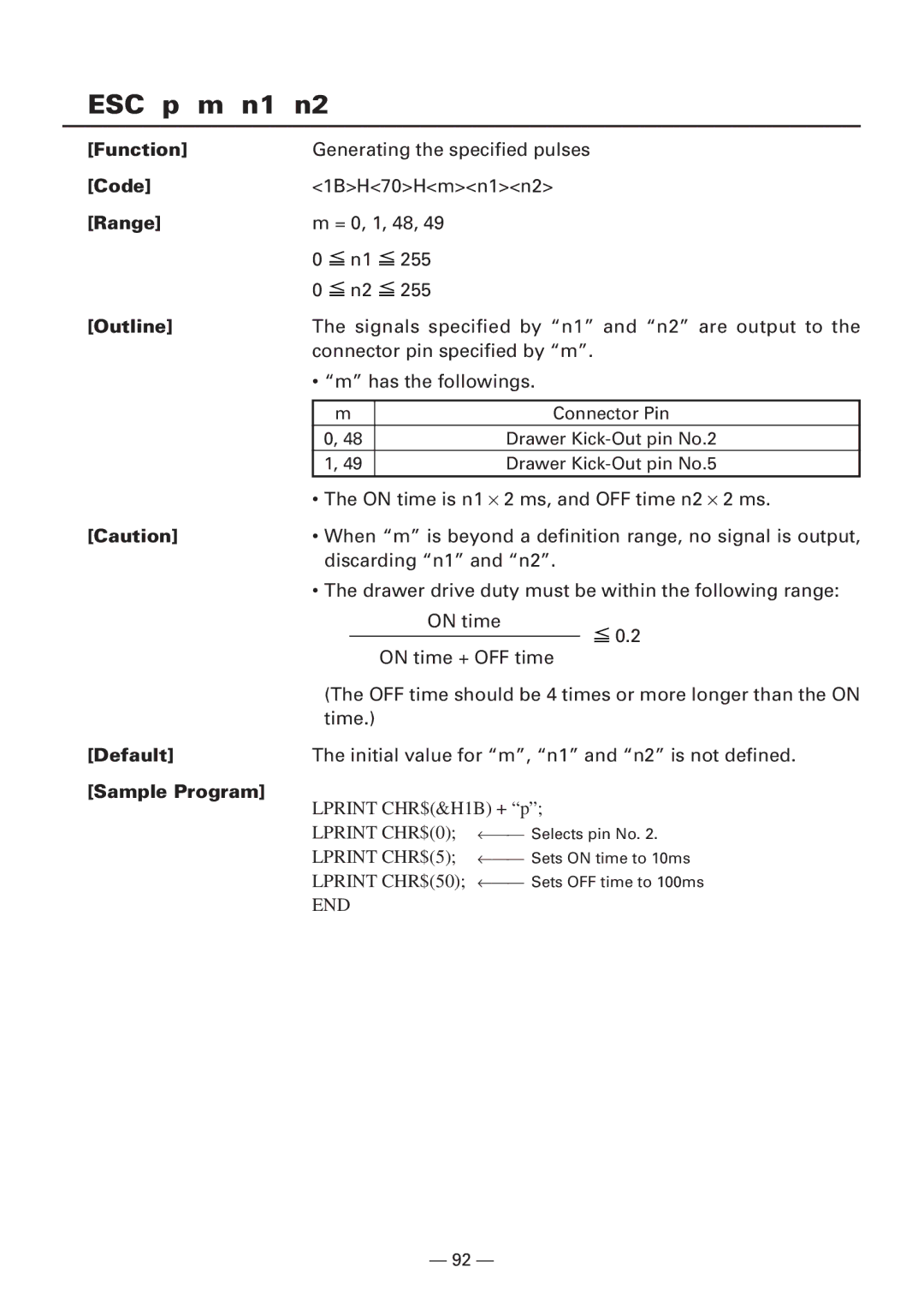
ESC p m n1 n2
’ ∝ ← n =
ESC n
Horizontal Magnification
GS ! n
Vertical Magnification
Default See Also
GS $ nL nH
See Also ESC $, ESC T, ESC W, ESC \, GS P, GS \
GS * n1 n2 d n1 × n2 ×
Next I Next J Return
GS a pL pH n m
Definition
GS / m
Specifying starting/ending macro definition
GS B n
GS H n
105
GS I n
GS L nL nH
GS P x y
ESC SP, ESC $, ESC W, ESC \
1DH56Hm
GS W nL nH
Default NL=64, nH=3 See Also
GS \ nL nH
GS n1 n2 n3
GS a n
Paper not found by Paper Near-end Sensor
Appendix
GS f n
Selecting bar code height
D1 ..... dk NUL
D1 ...... dn
For Standard Mode
For
For page Mode
Default Initial value is not defined
Description of Bar Codes For print examples, refer to
UPC-A
Ascii
This bar code consists of 103 bar code characters
Special characters
FNC4
Description of Bar Codes
When the serial interface is used
GS r n
Undefined Unused Fixed at
GS v 0 m xL xH yL yH d1...dk
130
GS w n
FS g3 m a1 a2 a3 a4 nL nH d1…dk
Range
Reference
FS g4 m a1 a2 a3 a4 nL nH
FS g3
P n m
Page
Q n xL xH yL yH d1…dk 1… xL xH yL yH d1…dk n
Page
Related Commands
Character Codes Table
Code
Codepage Katakana Japanese
Codepage PC850 Multilingual
Codepage PC860 Portuguese
Codepage PC863 Canadian-French
Codepage PC865 Nordic
Codepage PC852 Eastern Europe
Codepage PC866 Russian
Codepage PC857 Turkish
Windows Codepage
International Character Codes Table
Switching Between Standard Mode and page Mode
Appendix 1. page Mode
Overview
Mapping of print data in the print area
Mapping Position for Character Data
Mapping Positions for Print Data
Example of the Use of page Mode
156
157
Parallel Interface Communication Modes
Interfacing Phases
Negotiation
Negotiation Procedure
Overview
Precautions
Nibble Mode
Data Communication from Printer to Host
Byte Mode
Device ID
Termination
Page
Appendix 3. Identification of Send Status
Identification of Send Status
Appendix 4. Outline Drawing
15.1 iDP3240
AC Adapter 31AD
Appendix 5. Block Diagram
ROM LED
German
Allgemeine Vorsichtsmassnahmen
Warnung
Warnung
Vorsichtsmassnahmen FÜR DIE Installation
Vorsichtsmassnahmen FÜR DIE Handhabung
Heisser Bereich
Tägliche Wartungsarbeiten
Reinigen des Druckkopfs
Betrieb
Anschließen des Netzteils und Netzkabels
Anschließen der Schnittstellenkabel
Schalten Sie die Stromversorgung
Anschließen des Drawer Kickout-Steckers
Des Druckers aus
Einlegen / Auswechseln von Papierrollen
Einlegen von Papierrollen
183
184
185
Entfernen von Papierrollenresten
Öffnen Sie die Druckerabdeckung
Walzenhebel an. Anschließend kann
Beseitigen von Papierstaus
Die Papierwalze herausgehoben
Freigeben eines verriegelten Papierschneiders
Reinigen des Druckkopfes
Setzen Sie die Papierwalze wieder ein
Anzeigeleuchte Power Grün
Anzeigeleuchte Error Rot
Bedienungsfeld und Fehleranzeige
Fehleranzeige
Fehlerbeschreibung
Taste Feed
Drucktest
Durchführen des Drucktests
Funktion zur Erstellung eines hexadezimalen Speicherauszugs
Hexdump
Beispiel eines Hexdump
Einstellen DER DIP-SCHALTER
Position der DIP-Schalter
DIP-Schalter
DIP-Schaltertabelle
Druckdichte DIP-Schalter
Wählen der Zeichencodetabellen DIP-Schalter
Baud-Rate DIP-Schalter
Parallele Schnittstelle
Bidirektionale parallele Schnittstelle IEEE1284
Reverse-Modus Drucker → Hostkommunikation
Kurzbeschreibung
Belegung der Anschlußstifte
Eingangs- und Ausgangssignale
Druckereingangssignale
Druckerausgangssignale
Stromversorgungssignal
Eingangssignalpegel nStrobe, Data
Ausgangssignalpegel
Elektrische Kenndaten
Eingangs- und Ausgangsbedingungen
Timing-Tabelle KompatibilitätsModus
Datenempfangssteuerung
Datenpufferspeicher
Timing von Dateneingang und Datendruck
Serielle Schnittstelle
Technische Daten
Belegung der Anschlußstifte
Beschreibung der Eingangs- und Ausgangssignale
Fehlererkennung
Pufferung
DÜ-Blockfehler
Paritätsfehler
RS-232C-Schaltkreis
Drawer KickOut-Treibersignal
Technische Daten des Drawer KickOut-Anschlusses
Treiberschaltung
Technische Daten des Stromanschlusses
Stiftbelegung des Netzanschlusses
Wartung UND Kundendienst