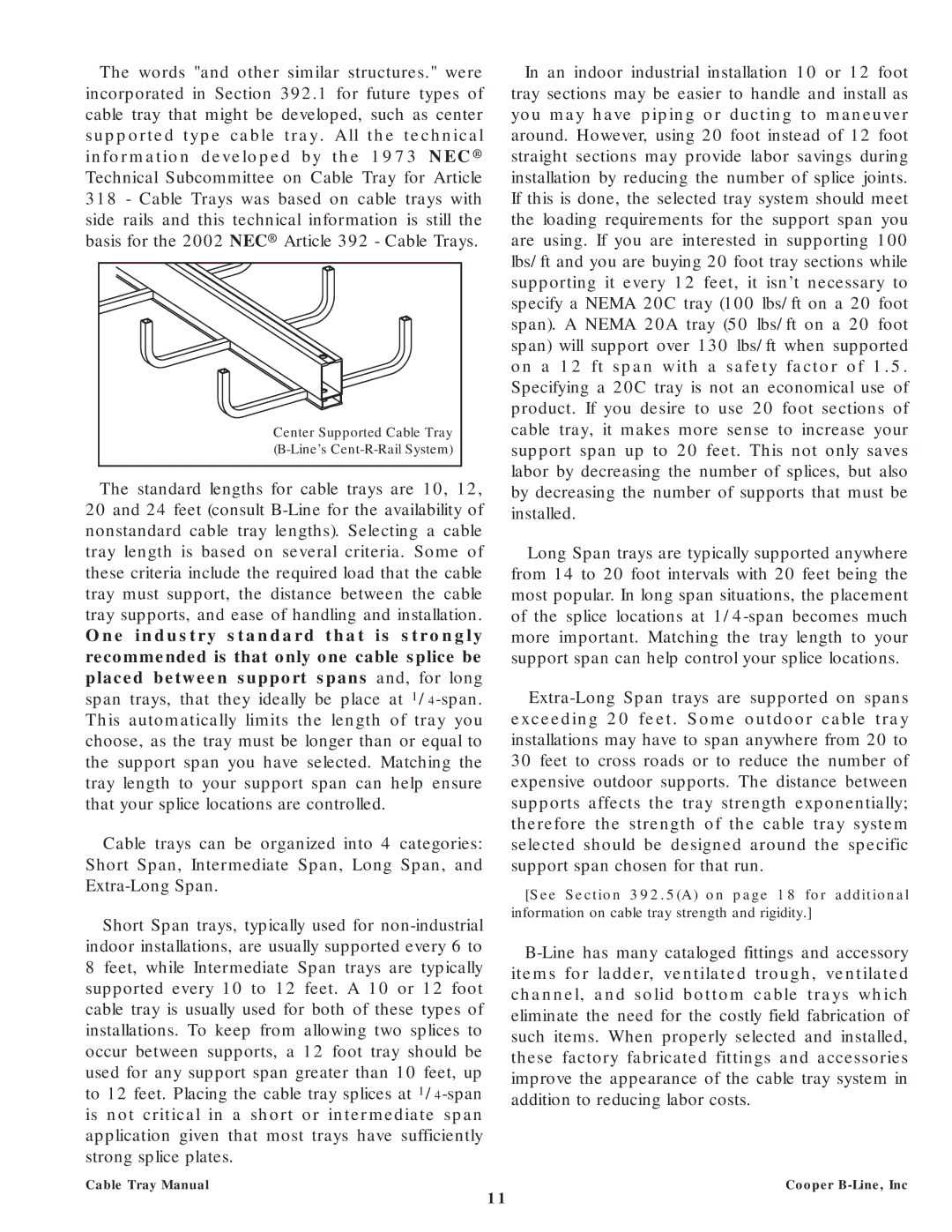
The words "and other similar structures." were incorporated in Section 392.1 for future types of cable tray that might be developed, such as center supported type cable tray. All the technical information developed by the 1973 NEC® Technical Subcommittee on Cable Tray for Article 318 - Cable Trays was based on cable trays with side rails and this technical information is still the basis for the 2002 NEC® Article 392 - Cable Trays.
Center Supported Cable Tray |
(B-Line’s Cent-R-Rail System) |
The standard lengths for cable trays are 10, 12, 20 and 24 feet (consult B-Line for the availability of nonstandard cable tray lengths). Selecting a cable tray length is based on several criteria. Some of these criteria include the required load that the cable tray must support, the distance between the cable tray supports, and ease of handling and installation. One industry standard that is strongly recommended is that only one cable splice be placed between support spans and, for long span trays, that they ideally be place at 1/4-span. This automatically limits the length of tray you choose, as the tray must be longer than or equal to the support span you have selected. Matching the tray length to your support span can help ensure that your splice locations are controlled.
Cable trays can be organized into 4 categories: Short Span, Intermediate Span, Long Span, and Extra-Long Span.
Short Span trays, typically used for non-industrial indoor installations, are usually supported every 6 to 8 feet, while Intermediate Span trays are typically supported every 10 to 12 feet. A 10 or 12 foot cable tray is usually used for both of these types of installations. To keep from allowing two splices to occur between supports, a 12 foot tray should be used for any support span greater than 10 feet, up to 12 feet. Placing the cable tray splices at 1/4-span is not critical in a short or intermediate span application given that most trays have sufficiently strong splice plates.
Cable Tray Manual
In an indoor industrial installation 10 or 12 foot tray sections may be easier to handle and install as you may have piping or ducting to maneuver around. However, using 20 foot instead of 12 foot straight sections may provide labor savings during installation by reducing the number of splice joints. If this is done, the selected tray system should meet the loading requirements for the support span you are using. If you are interested in supporting 100 lbs/ft and you are buying 20 foot tray sections while supporting it every 12 feet, it isn’t necessary to specify a NEMA 20C tray (100 lbs/ft on a 20 foot span). A NEMA 20A tray (50 lbs/ft on a 20 foot span) will support over 130 lbs/ft when supported on a 12 ft span with a safety factor of 1.5. Specifying a 20C tray is not an economical use of product. If you desire to use 20 foot sections of cable tray, it makes more sense to increase your support span up to 20 feet. This not only saves labor by decreasing the number of splices, but also by decreasing the number of supports that must be installed.
Long Span trays are typically supported anywhere from 14 to 20 foot intervals with 20 feet being the most popular. In long span situations, the placement of the splice locations at 1/4-span becomes much more important. Matching the tray length to your support span can help control your splice locations.
Extra-Long Span trays are supported on spans exceeding 20 feet. Some outdoor cable tray installations may have to span anywhere from 20 to 30 feet to cross roads or to reduce the number of expensive outdoor supports. The distance between supports affects the tray strength exponentially; therefore the strength of the cable tray system selected should be designed around the specific support span chosen for that run.
[See Section 392.5(A) on page 18 for additional information on cable tray strength and rigidity.]
B-Line has many cataloged fittings and accessory items for ladder, ventilated trough, ventilated channel, and solid bottom cable trays which eliminate the need for the costly field fabrication of such items. When properly selected and installed, these factory fabricated fittings and accessories improve the appearance of the cable tray system in addition to reducing labor costs.
Cooper B-Line, Inc