high amperage short circuit if a low resistance metallic path (metallic cable tray or metallic raceway) is present
Nonmetallic Cable Trays].
392.4. Uses Not Permitted.
This is the only place in the NEC® where all the various types of cable tray have limitations on their place of use. No cable trays can be used in hoistways or where subject to severe physical damage. The designer must identify the zones of installation where a cable tray might be subjected to severe physical damage. Usually such areas are limited and provisions can be made to protect the cable tray by relocating it to a more desirable location or as a last resort to provide protection using the appropriate structural members.
The second sentence of Section 392.4 states that cable tray shall not be used in environmental air spaces except to support the wiring methods recognized for use in such spaces. This is not a restriction on cable tray as long as it is used as a support for the appropriate cable types.
Metallic cable trays may support cable types approved for installation in Ducts or Plenums Used for Environmental Air as per Section 300.22(B) and the cable types approved for installation in Other Space Used for Environmental Air as per Section 300.22(C).
The second sentence of Section 300.22(C)(1) is as follows:
Other types of cables and conductors shall be installed in electrical metallic tubing, flexible metallic tubing, intermediate metal conduit, rigid metal conduit without an overall nonmetallic covering, flexible metal conduit, or, where accessible, surface metal raceway or metal wireway with metal covers or solid bottom metal cable tray with solid metal covers.
Reprinted with permission from NFPA
This part of Section 300.22(C) is confusing. The statement as underlined in the above paragraph leads some to assume, for installations in Other Spaces Used for Environmental Air, that the types of insulated single conductors which are installed in raceway installations may also be installed in solid bottom metal cable trays with metal covers. This is
Cooper B-Line, Inc
not so. Only the appropriate multiconductor cable types as per Section 392.3(A) may be installed in solid bottom cable trays.
Cable tray may be used to support data process wiring systems in air handling areas below raised floors as per Sections 300.22(D) and 800.52(D).
392.5.Construction Specifications. (A) Strength and Rigidity.
The designer must properly select a structurally satisfactory cable tray for their installation. This selection is based on the cable tray's strength, the cable tray loading and the spacing of the supports. The NEMA Metallic Cable Tray Systems Standard Publication
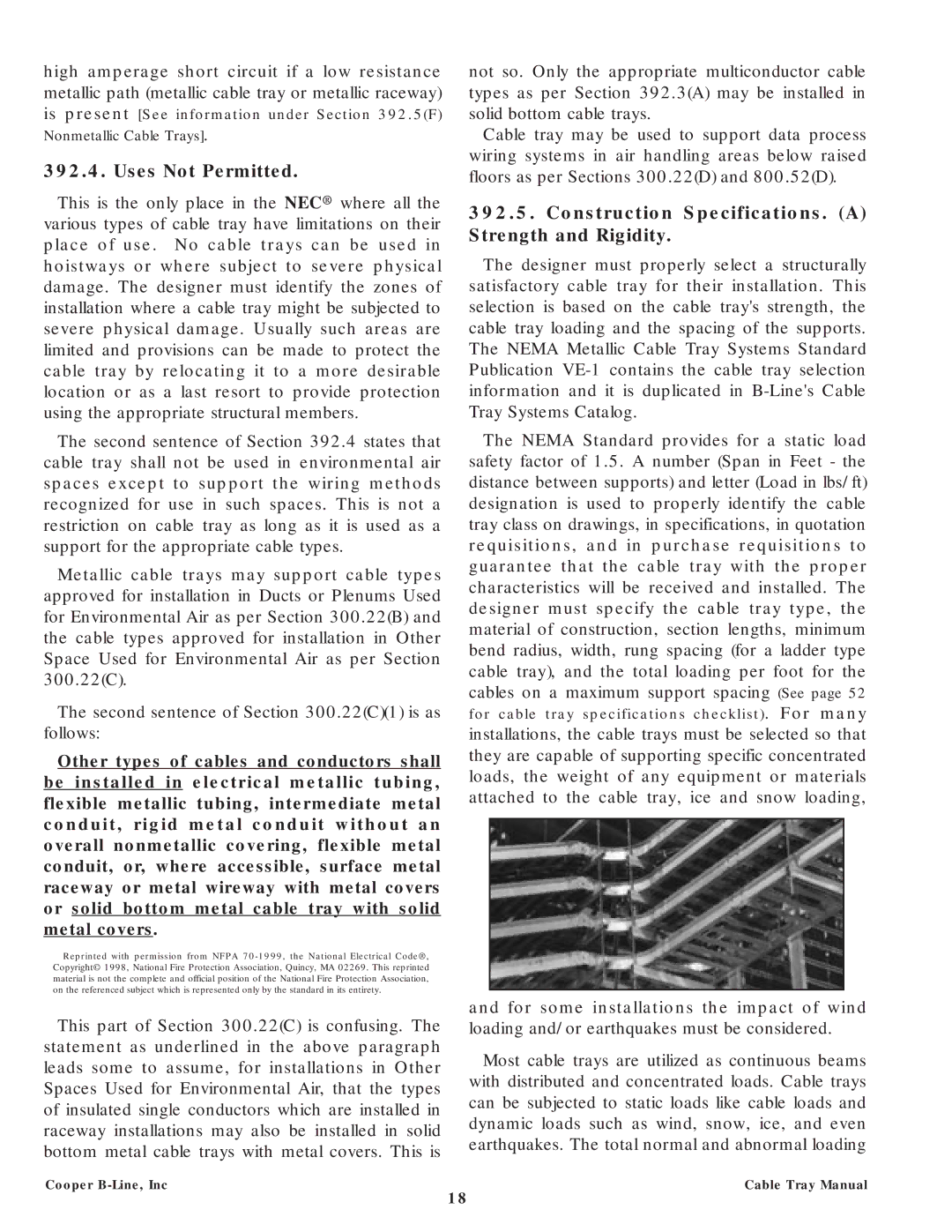
The NEMA Standard provides for a static load safety factor of 1.5. A number (Span in Feet - the distance between supports) and letter (Load in lbs/ft) designation is used to properly identify the cable tray class on drawings, in specifications, in quotation requisitions, and in purchase requisitions to guarantee that the cable tray with the proper characteristics will be received and installed. The designer must specify the cable tray type, the material of construction, section lengths, minimum bend radius, width, rung spacing (for a ladder type cable tray), and the total loading per foot for the cables on a maximum support spacing (See page 52 for cable tray specifications checklist). For many installations, the cable trays must be selected so that they are capable of supporting specific concentrated loads, the weight of any equipment or materials attached to the cable tray, ice and snow loading,
and for some installations the impact of wind loading and/or earthquakes must be considered.
Most cable trays are utilized as continuous beams with distributed and concentrated loads. Cable trays can be subjected to static loads like cable loads and dynamic loads such as wind, snow, ice, and even earthquakes. The total normal and abnormal loading
Cable Tray Manual
18