There are some designers, engineers, and inspectors that do not think that cable tray is a mechanical support system just as strut is a mechanical support system. Cable tray is not a raceway in the NEC® but some designers, engineers, and inspectors attempt to apply the requirements for raceway wiring systems to cable tray wiring systems even when they are not applicable. Cable tray wiring systems have been used by American industry for over 35 years with outstanding safety and continuity of service records. The safety service record of cable tray wiring systems in industrial facilities has been significantly better than those of conduit wiring systems. There have been industrial fires and explosions that have occurred as a direct result of the wiring system being a conduit wiring system. In these cases, cable tray wiring systems would not have provided the fires and explosions that the conduit systems did by providing as explosion gas flow path to the ignition source even though the conduit systems contained seals.
The most significant part of this section is that the metallic cable tray system must have electrical continuity over its entire length and that the support for the cables must be maintained. These requirements can be adequately met even though there will be installation conditions where the cable tray is mechanically discontinuous, such as at a firewall penetration, at an expansion gap in a long straight cable tray run, where there is a change in elevation of a few feet between two horizontal cable tray sections of the same run, or where the cables drop from an overhead cable tray to enter equipment. In all these cases, adequate bonding jumpers must be used to bridge the mechanical discontinuity.
Control Cable Entering Pushbutton and Power Cable Entering Motor Terminal Box from 6 Inch Channel Cable Tray System
(Bottom entries provide drip loops to prevent moisture flow into enclosures.)
Cooper B-Line, Inc
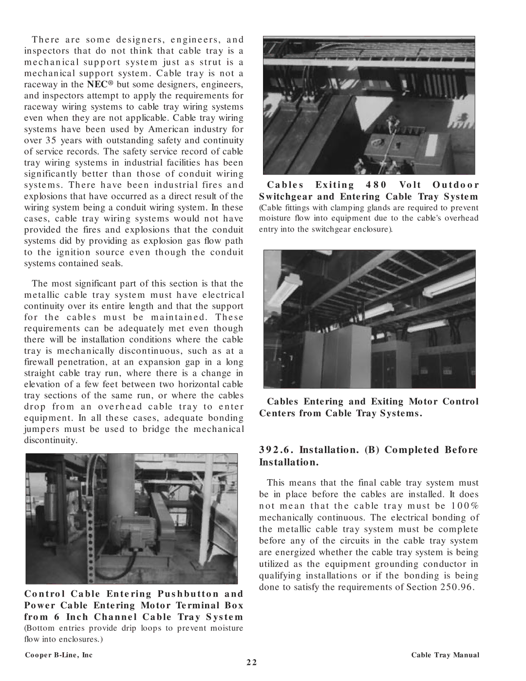
Cables Exiting 480 Volt Outdoor Switchgear and Entering Cable Tray System
(Cable fittings with clamping glands are required to prevent moisture flow into equipment due to the cable's overhead entry into the switchgear enclosure).
Cables Entering and Exiting Motor Control Centers from Cable Tray Systems.
392.6.Installation. (B) Completed Before Installation.
This means that the final cable tray system must be in place before the cables are installed. It does not mean that the cable tray must be 100% mechanically continuous. The electrical bonding of the metallic cable tray system must be complete before any of the circuits in the cable tray system are energized whether the cable tray system is being utilized as the equipment grounding conductor in qualifying installations or if the bonding is being done to satisfy the requirements of Section 250.96.
Cable Tray Manual
22