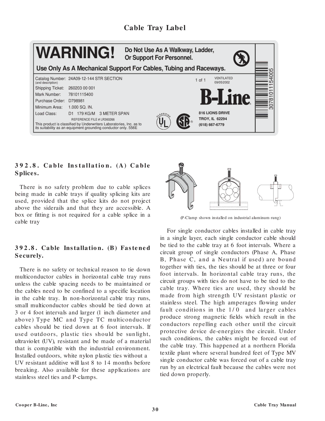
Cable Tray Label
WARNING! Do Not Use As A Walkway, Ladder, Or Support For Personnel.
Use Only As A Mechanical Support For Cables, Tubing and Raceways.
Catalog Number: | |
(and description) |
|
Shipping Ticket: | 260203 00 001 |
Mark Number: | 78101115400 |
Purchase Order: | D798981 |
Minimum Area: | 1.000 SQ. IN. |
Load Class: | D1 179 KG/M 3 METER SPAN |
REFERENCE FILE # LR360266
This product is classified by Underwriters Laboratories, Inc. as to its suitability as an equipment grounding conductor only. 556E
1 of 1 | VENTILATED | |
09/05/2002 | ||
|
816 LIONS DRIVE
TROY, IL 62294
(618)
30781011154005
392.8. Cable Installation. (A) Cable Splices.
There is no safety problem due to cable splices being made in cable trays if quality splicing kits are used, provided that the splice kits do not project above the siderails and that they are accessible. A box or fitting is not required for a cable splice in a cable tray
392.8.Cable Installation. (B) Fastened Securely.
There is no safety or technical reason to tie down multiconductor cables in horizontal cable tray runs unless the cable spacing needs to be maintained or the cables need to be confined to a specific location in the cable tray. In
For single conductor cables installed in cable tray in a single layer, each single conductor cable should be tied to the cable tray at 6 foot intervals. Where a circuit group of single conductors (Phase A, Phase B, Phase C, and a Neutral if used) are bound together with ties, the ties should be at three or four foot intervals. In horizontal cable tray runs, the circuit groups with ties do not have to be tied to the cable tray. Where ties are used, they should be made from high strength UV resistant plastic or stainless steel. The high amperages flowing under fault conditions in the 1/0 and larger cables produce strong magnetic fields which result in the conductors repelling each other until the circuit protective device
Cooper | Cable Tray Manual |
30