support. Although the use of cable tray fittings is not mandatory, it is often desirable to use them when possible to improve the appearance of the installation.
392.5.Construction Specifications. (F) Nonmetallic Cable Tray.
This type of cable tray is usually made of Fiberglass Reinforced Plastic (FRP). Applications for FRP cable tray systems include some corrosive atmospheres and where
to insure the longevity of the product. Ambient temperature is also a design consideration when FRP cable tray is used. An ambient temperature of 100°F will decrease the loading capacity of poltester resin fiberglass cable tray by 10%.
392.6. Installation. (A) Complete System.
This section states that cable tray systems can have mechanically discontinuous segments, and that the mechanically discontinuous segment cannot be greater than 6 feet. A bonding jumper sized per Section 250.102 is necessary to connect across any discontinuous segment. The bonding of the system should be in compliance with Section 250.96.
![]() Bonding
Bonding
Jumper
Cable Tray Elevation Change Without Fittings
|
|
|
| 6 | 8 |
|
|
|
|
|
|
|
|
| |
|
|
| 5 |
| 1 |
|
|
|
|
|
|
|
|
| |
|
|
|
|
|
|
| 16 |
|
|
|
| 10 |
| 2 | 7 |
|
|
|
|
|
|
| |
|
|
|
|
|
|
| 4 |
|
|
| 11 | 12 |
| 13 |
|
|
|
|
| 9 |
|
|
|
|
|
|
| 18 |
|
| 3 |
|
|
|
|
|
|
| |
|
|
|
|
|
|
| 15 |
|
|
|
| 17 |
| 14 |
|
|
|
|
|
|
|
| |
|
|
|
|
|
|
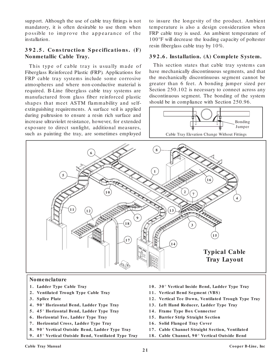
| Typical Cable |
|
|
|
|
|
|
| Tray Layout |
|
|
|
|
|
|
| |
|
|
|
|
|
|
|
|
|
| Nomenclature |
|
|
|
| |
|
| 1. | Ladder Type Cable Tray | 10. | 30° Vertical Inside Bend, Ladder Type Tray | ||
|
| 2. | Ventilated Trough Type Cable Tray | 11. | Vertical Bend Segment (VBS) | ||
|
| 3. | Splice Plate |
| 12. | Vertical Tee Down, Ventilated Trough Type Tray | |
|
| 4. | 90° Horizontal Bend, Ladder Type Tray | 13. | Left Hand Reducer, Ladder Type Tray | ||
|
| 5. | 45° Horizontal Bend, Ladder Type Tray | 14. | Frame Type Box Connector | ||
|
| 6. | Horizontal Tee, Ladder Type Tray | 15. | Barrier Strip Straight Section | ||
|
| 7. | Horizontal Cross, Ladder Type Tray | 16. | Solid Flanged Tray Cover | ||
|
| 8. | 90° Vertical Outside Bend, Ladder Type Tray | 17. | Cable Channel Straight Section, Ventilated | ||
|
| 9. | 45° Vertical Outside Bend, Ventilated Type Tray | 18. | Cable Channel, 90° Vertical Outside Bend | ||
|
|
|
|
|
|
| |
Cable Tray Manual |
|
|
| Cooper | |||
21