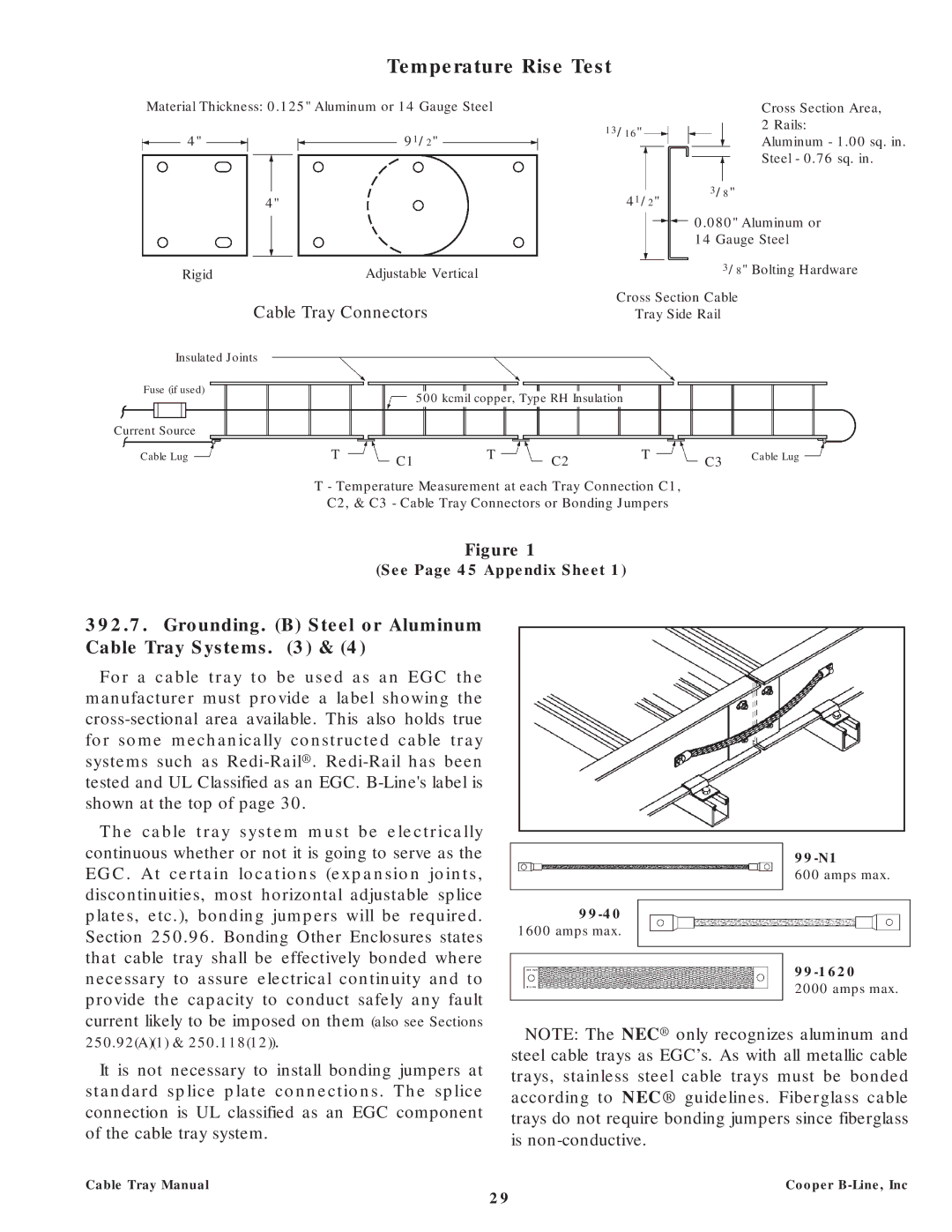
Temperature Rise Test
Material Thickness: 0.125" Aluminum or 14 Gauge Steel |
| Cross Section Area, | ||||
|
|
|
|
| 13/16" | 2 Rails: |
|
|
|
|
| ||
| 4" |
| 91/2" |
| Aluminum - 1.00 sq. in. | |
|
|
|
| |||
Steel - 0.76 sq. in.
|
|
|
|
|
|
|
|
|
|
|
|
|
|
|
|
|
| 3/8" |
| ||
|
|
|
|
|
|
|
|
|
|
|
|
|
| 41/2" |
| ||||||
|
| 4" |
|
|
|
|
|
|
|
|
|
|
|
| |||||||
|
|
|
|
|
|
|
|
|
|
|
|
|
|
|
|
| |||||
|
|
|
|
|
|
|
|
|
|
|
|
|
|
|
|
|
| 0.080" Aluminum or | |||
|
|
|
|
|
|
|
|
|
|
|
|
|
|
|
|
|
| 14 Gauge Steel | |||
Rigid |
|
|
|
| Adjustable Vertical |
|
|
|
|
|
|
|
|
| 3/8" Bolting Hardware | ||||||
| Cable Tray Connectors |
|
|
| Cross Section Cable |
| |||||||||||||||
|
|
|
|
|
|
| Tray Side Rail |
| |||||||||||||
Insulated Joints |
|
|
|
|
|
|
|
|
|
|
|
|
|
|
|
|
| ||||
Fuse (if used) |
|
|
|
|
|
|
|
|
|
|
|
|
|
|
|
|
|
|
|
|
|
|
|
|
|
|
| 500 kcmil copper, Type RH Insulation |
|
|
|
|
|
|
| ||||||||
|
|
|
|
|
|
|
|
|
|
|
| ||||||||||
Current Source |
|
|
|
|
|
|
|
|
|
|
|
|
|
|
|
|
|
|
|
|
|
|
|
|
|
|
|
|
|
|
|
|
|
|
|
|
|
|
|
|
|
|
|
Cable Lug |
|
|
| T |
|
|
|
|
| T |
|
|
| T |
|
|
| Cable Lug | |||
|
|
| C1 |
|
|
| C2 |
|
| C3 |
| ||||||||||
|
|
|
|
|
|
|
|
|
|
|
|
|
|
|
|
|
| ||||
|
|
|
|
|
|
|
|
|
|
|
|
|
|
| |||||||
|
|
|
|
|
|
|
|
|
|
|
|
|
|
|
|
|
|
|
|
|
|
T - Temperature Measurement at each Tray Connection C1,
C2, & C3 - Cable Tray Connectors or Bonding Jumpers
Figure 1
(See Page 45 Appendix Sheet 1)
392.7.Grounding. (B) Steel or Aluminum Cable Tray Systems. (3) & (4)
For a cable tray to be used as an EGC the manufacturer must provide a label showing the
The cable tray system must be electrically continuous whether or not it is going to serve as the EGC. At certain locations (expansion joints, discontinuities, most horizontal adjustable splice plates, etc.), bonding jumpers will be required. Section 250.96. Bonding Other Enclosures states that cable tray shall be effectively bonded where necessary to assure electrical continuity and to provide the capacity to conduct safely any fault current likely to be imposed on them
1600 amps max.
600 amps max.
2000 amps max.
250.92(A)(1) & 250.118(12)).
It is not necessary to install bonding jumpers at standard splice plate connections. The splice connection is UL classified as an EGC component of the cable tray system.
NOTE: The NEC® only recognizes aluminum and steel cable trays as EGC’s. As with all metallic cable trays, stainless steel cable trays must be bonded according to NEC® guidelines. Fiberglass cable trays do not require bonding jumpers since fiberglass is
Cable Tray Manual | Cooper |
29