392.7.Grounding. (B) Steel or Aluminum Cable Tray Systems. (1) & (2)
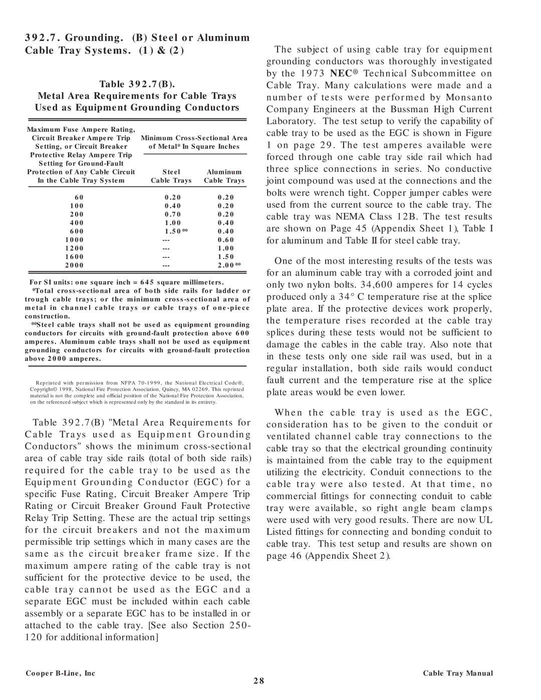
Table 392.7(B).
Metal Area Requirements for Cable Trays Used as Equipment Grounding Conductors
Maximum Fuse Ampere Rating, |
|
|
|
| |
| Circuit Breaker Ampere Trip | Minimum | |||
| Setting, or Circuit Breaker |
| of Metal* In Square Inches | ||
| Protective Relay Ampere Trip |
|
|
|
|
|
|
|
|
| |
| Setting for |
|
|
|
|
Protection of Any Cable Circuit |
| Steel | Aluminum | ||
| In the Cable Tray System |
| Cable Trays | Cable Trays | |
|
|
|
|
|
|
60 | 0.20 | 0.20 |
| ||
100 | 0.40 | 0.20 |
| ||
200 | 0.70 | 0.20 |
| ||
400 | 1.00 | 0.40 |
| ||
600 | 1.50** | 0.40 |
| ||
1000 | 0.60 |
| |||
1200 | 1.00 |
| |||
1600 | 1.50 |
| |||
2000 | 2.00** |
| |||
|
|
|
|
|
|
|
|
|
|
|
|
For SI units: one square inch = 645 square millimeters.
*Total
**Steel cable trays shall not be used as equipment grounding conductors for circuits with
Reprinted with permission from NFPA
Table 392.7(B) "Metal Area Requirements for Cable Trays used as Equipment Grounding Conductors" shows the minimum
Cooper B-Line, Inc
The subject of using cable tray for equipment grounding conductors was thoroughly investigated by the 1973 NEC® Technical Subcommittee on Cable Tray. Many calculations were made and a number of tests were performed by Monsanto Company Engineers at the Bussman High Current Laboratory. The test setup to verify the capability of cable tray to be used as the EGC is shown in Figure 1 on page 29. The test amperes available were forced through one cable tray side rail which had three splice connections in series. No conductive joint compound was used at the connections and the bolts were wrench tight. Copper jumper cables were used from the current source to the cable tray. The cable tray was NEMA Class 12B. The test results are shown on Page 45 (Appendix Sheet 1), Table I for aluminum and Table II for steel cable tray.
One of the most interesting results of the tests was for an aluminum cable tray with a corroded joint and only two nylon bolts. 34,600 amperes for 14 cycles produced only a 34° C temperature rise at the splice plate area. If the protective devices work properly, the temperature rises recorded at the cable tray splices during these tests would not be sufficient to damage the cables in the cable tray. Also note that in these tests only one side rail was used, but in a regular installation, both side rails would conduct fault current and the temperature rise at the splice plate areas would be even lower.
When the cable tray is used as the EGC, consideration has to be given to the conduit or ventilated channel cable tray connections to the cable tray so that the electrical grounding continuity is maintained from the cable tray to the equipment utilizing the electricity. Conduit connections to the cable tray were also tested. At that time, no commercial fittings for connecting conduit to cable tray were available, so right angle beam clamps were used with very good results. There are now UL Listed fittings for connecting and bonding conduit to cable tray. This test setup and results are shown on page 46 (Appendix Sheet 2).
Cable Tray Manual
28