CABLE TRAY. THERMAL CONTRACTION AND EXPANSION
All materials expand and contract due to temperature changes. Cable tray installations should incorporate features which provide adequate compensation for thermal contraction and expansion. Installing expansion joints in the cable tray runs only at the structure expansion joints does not normally compensate adequately for the cable tray's thermal contraction and expansion. The supporting structure material and the cable tray material will have different thermal expansion values. They each require unique solutions to control thermal expansion.
NEC® Section 300.7(B) states that 'Raceways shall be provided with expansion joints where necessary to compensate for thermal expansion or contraction.' NEC® Section 392 does not address thermal contraction and expansion of cable tray. One document which addresses expansion is the NEMA Standards Publication No. VE 2, Section 4.3.2. NEMA
Reprinted with permission from NFPA
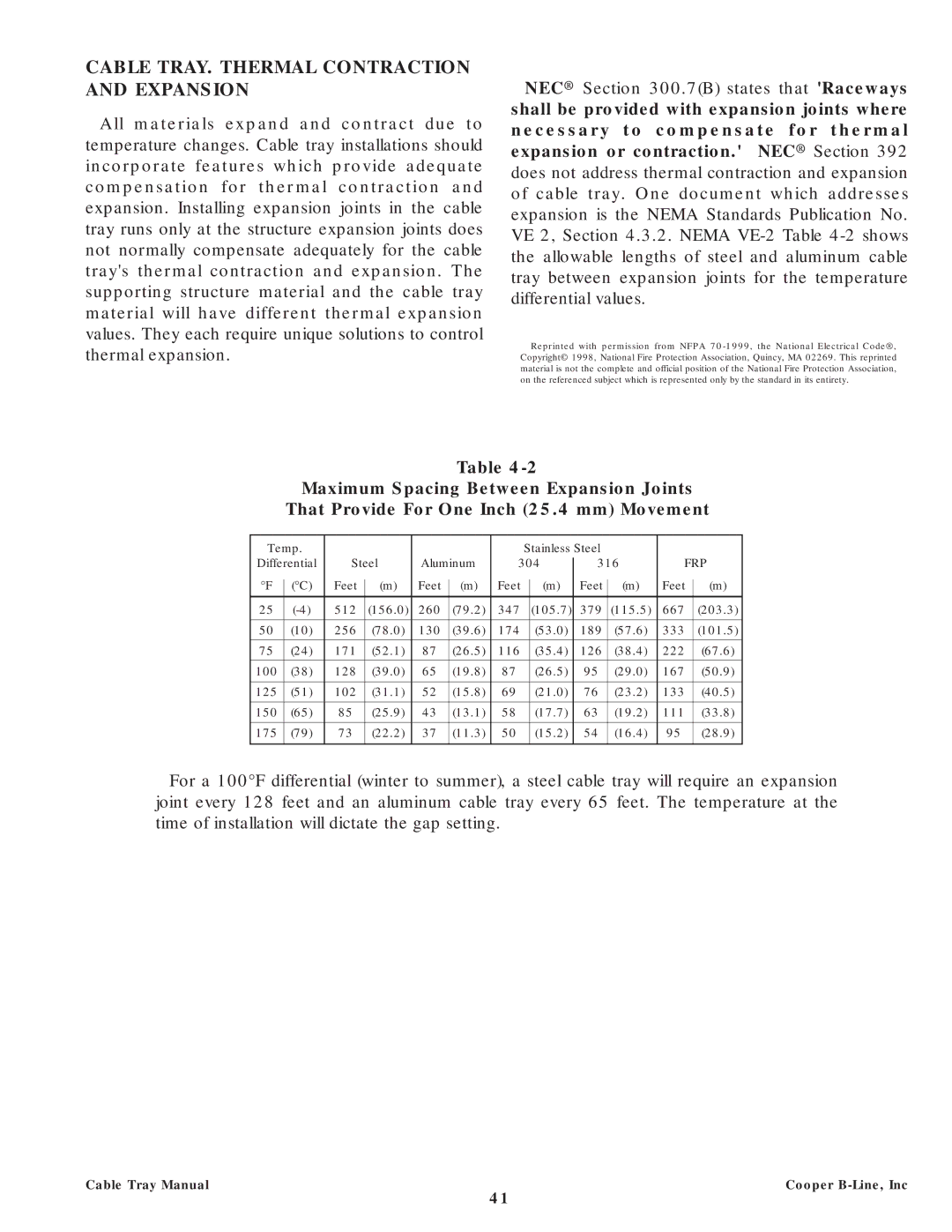
Table
Maximum Spacing Between Expansion Joints
That Provide For One Inch (25.4 mm) Movement
Temp. |
|
|
|
|
|
|
| Stainless Steel |
|
|
|
|
| |||||
Differential | Steel | Aluminum | 304 |
| 316 | FRP | ||||||||||||
| ||||||||||||||||||
°F |
| (°C) | Feet |
| (m) | Feet |
| (m) | Feet |
| (m) |
| Feet |
| (m) | Feet |
| (m) |
|
|
|
|
|
|
| ||||||||||||
|
|
|
|
|
|
|
|
|
|
|
|
|
|
|
|
|
|
|
25 |
| 512 |
| (156.0) | 260 |
| (79.2) | 347 |
| (105.7) |
| 379 |
| (115.5) | 667 |
| (203.3) | |
|
|
|
|
|
|
|
|
|
|
|
|
|
|
|
|
|
|
|
50 |
| (10) | 256 |
| (78.0) | 130 |
| (39.6) | 174 |
| (53.0) |
| 189 |
| (57.6) | 333 |
| (101.5) |
|
|
|
|
|
|
|
|
|
|
|
|
|
|
|
|
|
|
|
75 |
| (24) | 171 |
| (52.1) | 87 |
| (26.5) | 116 |
| (35.4) |
| 126 |
| (38.4) | 222 |
| (67.6) |
|
|
|
|
|
|
|
|
|
|
|
|
|
|
|
|
|
|
|
100 |
| (38) | 128 |
| (39.0) | 65 |
| (19.8) | 87 |
| (26.5) |
| 95 |
| (29.0) | 167 |
| (50.9) |
|
|
|
|
|
|
|
|
|
|
|
|
|
|
|
|
|
|
|
125 |
| (51) | 102 |
| (31.1) | 52 |
| (15.8) | 69 |
| (21.0) |
| 76 |
| (23.2) | 133 |
| (40.5) |
|
|
|
|
|
|
|
|
|
|
|
|
|
|
|
|
|
|
|
150 |
| (65) | 85 |
| (25.9) | 43 |
| (13.1) | 58 |
| (17.7) |
| 63 |
| (19.2) | 111 |
| (33.8) |
|
|
|
|
|
|
|
|
|
|
|
|
|
|
|
|
|
|
|
175 |
| (79) | 73 |
| (22.2) | 37 |
| (11.3) | 50 |
| (15.2) |
| 54 |
| (16.4) | 95 |
| (28.9) |
|
|
|
|
|
|
|
|
|
|
|
|
|
|
|
|
|
|
|
For a 100°F differential (winter to summer), a steel cable tray will require an expansion joint every 128 feet and an aluminum cable tray every 65 feet. The temperature at the time of installation will dictate the gap setting.
Cable Tray Manual | Cooper |
41