113.248320
Save This Manual For Future Reference
113.248440113.248510
Table of Contents
Keep Guards in Place
Know Your Power Tool Ground ALL Tools
Keep Work Area Clean
USE Recommended Accessories Never Stand on Tool
Before Each USE
Additional safety instructions for band saw
Before Using the SAW
When Installing or Moving the SAW
Before Sanding
Accessories
Whenever SAW is Running
Glossary of terms for woodworking
Power Supply
25 Ft 26 50 Ft 100 Ft
Motor Safety Protection
Wire Sizes
Sawdust from interfering with normal motor ventila- tion
General information
Unpacking and checking contents
Description QTY
Loose Parts
Pan Hd. Screw 10-32 x
List of Loose Parts in BAG #507968
Truss Head Screw 1/4-20x12
List of Loose Parts in BAG #508014
Nuts Support Bracke Leveling Foot
Assembly and alignment
Attaching LEG SET
Model 113.24821 O
Description Qty Truss Head
Assembling Cabinet
Model
\ ,/o
From loose parts bag find the following hard
Mounting the SAW to the Cabinet
Ware
Front
Find the following parts
Model 113.248210 only
Attaching the Handwheel
Mounting the Motor
Models 113.248440,
Tighten Flange NUT After Tensioning Beltwith Wing NUT
Steps are Completed
Connecting the Motor
Selecting Blade Speed
Recommended Speed Settings
Changing Speed Settings
Model 113.248320, 113.248440
Attaching Trim Caps
MODELS113.248210an¢
Getting to know your band saw
Model 113.248440 & 113.248510 on LY
Location and function of the electronic indicator system
Open Battery Open
Battery Cover
3000
Using the Electronic Indicator System
Function Keys
Read-out Indicates correct tension for
Jrt,t
Installing the Blade
Upperblade tl t
GU,DEsuPPO.TIIl-r L
Aligning the Blade and Blade Guide Assemblies
Model 113.248440
Blade Guide
4-20 8 hex washer Head thread forming Screws
Mounting Front
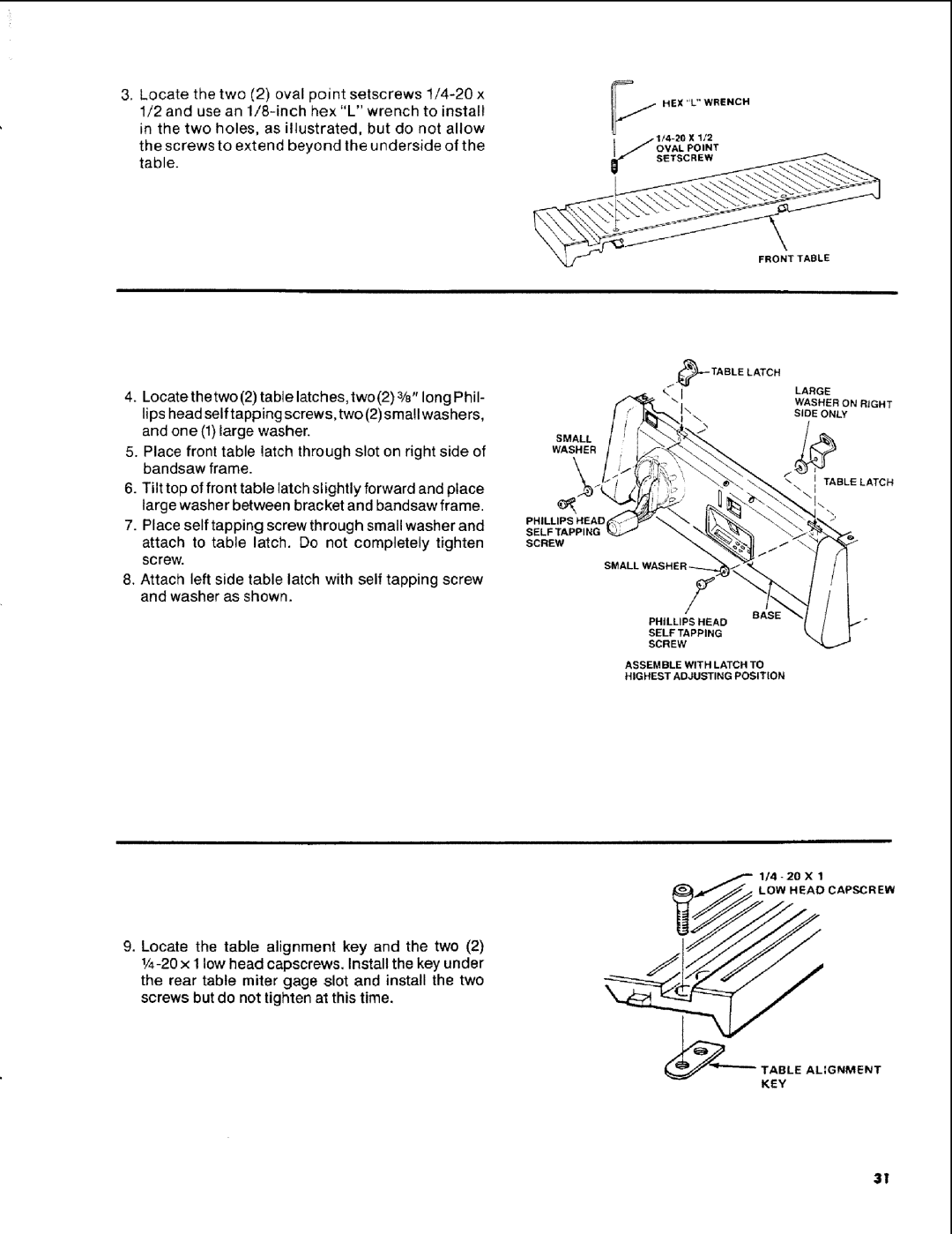
Turn front table over. Locate the two 2 latch
Springs, two 2 alignment springs, and the four
Head Capscrew
Squaring the Blade to the Table
Adjusting Front Table
Location and function of controls
ON-OFF Switch
Model 113.248210 & 113,248320
Adjusting Bevel Lock Knob
Operation Recommended Blade Size
Basic band saw operation
Sawdust Collection
Circle Cutting
Installing the Sanding Belt
Installing Sanding Attachment
Adjusting Band SAW Bevel Travel
Maintenance
Adjusting the Upper Blade Guide Travel
Light Bulb
Outlet Before Trouble Shooting Your Band SAW/SANDER
Remedy
Trouble shooting--motor
Trouble
Probable Cause
Problem
Trouble shooting -- electronics
Probable Cause Suggested Corrective Action
113.2485t
Trouble shooting ---electronics
Suggested Corrective Action
Leg
Repair parts
Parts List for Craftsman 12-INCH Band SAW
Key Part Description
Page
Key
Drive Assembly Parts
Model NOS .248210,113.248320, 113.248440
OMode1113.248320 Only ==Model113.248510 Only
Base Assembly
Model NOS .248210,113.248320,113.248440
9414202
Bevel Drive and Motor Mount Assembly Parts
Screw, Truss Hd /4-20 x 1/2
Parts List for Craftsman 12-INCH Electronic Band SAW
Page
Part Numberpartdescription Model Name of Item
Airs