INSTALLING CONTROL CUT DEVICE
See Figure 34.
Note: Before installing the control cut device, the yoke assembly will travel back and forward on the carriage by pulling the handle. After installing the control cut device, the power cord for the control cut device must be plugged in and switch trigger pressed to move the yoke assembly and carriage on the arm.
_k WARNING: Do not install the control cut device until after all of the initial adjustments and
alignments are made to prevent accidental starting of the saw that could result in serious personal injury.
The control cut device offers many benefits. As it increases operator control, it eliminates the risk in a cross cut of the saw "climbing" out and over the workpiece at the operator. Feed control of the blade as it cuts through the workpiece increases, as does the accuracy of the cut.
The control cut cable maintains a steady pull on the carriage assembly from the column. This tension keeps the assembly at the column, unless you squeeze the switch trigger in the handle. The switch trigger activates the motor to counter the pull of the cable.
After a cut is completed, press the switch on the arm off, then release the switch trigger to prevent further forward motion. Hold the handle until the blade has stopped rotating. The yoke assembly will not roll forward unless you are squeezing the switch trigger.
The control cut power cord is designed to operate on a single voltage AC circuit. The speed can be set with a thumbwheel on top of the handle. The three speed settings are described on the label located on the left side of the control cut housing.
,_ WARNING." Do not use the saw without the control cut and blade guards in place unless
specifically instructed to do so. Otherwise uncontrolled contact with the blade could occur, resulting in personal injury.
•Plug in the control cut cord, leaving the main power cord disconnected. Squeeze the switch trigger to confirm the control cut motor is receiving power.
•On the left side of the saw, remove the carriage lock knob and spring. Remove the two screws that attach the carriage cover and remove the cover.
•Replace the spdng and carriage lock knob. Pull the carriage assembly about halfway to the front.
Tighten the carriage lock knob.
•Squeeze the switch trigger in the handle with your right hand and pull the spring loaded cable from the column with your left hand. If you prefer to use a pair of pliers, do not damage the cable. Note: Do not to let the spring loaded cable clamp slip out of your hand or pliers. If it slips past the cable bracket and goes up into the control cut motor housing, then disassembly of the control cut assembly will be required to get it back out.
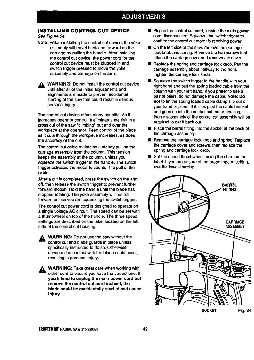
•Place the barrel fitting into the socket at the back of the carriage assembly.
nRemove the carriage lock knob and spdng. Replace the carriage cover and screws, then replace the spring and carriage lock knob.
•Set the speed thumbwheel, using the chart on the label. If you are unsure of the proper speed setting, use the lowest setting.
BARREL
CARRIAGE
ASSEMBLY
,_= WARNING: Take great care when working with either cord to ensure you have the correct one. If
you intend to unplug the main power cord but remove the control cut cord instead, the blade could be accidentally started and cause injury.
SOCKET | Fig. 34 |
CRRFTSMRN"RADIALSAW 315.220380 | 42 |