Back Panel Description
BACK PANEL DESCRIPTION
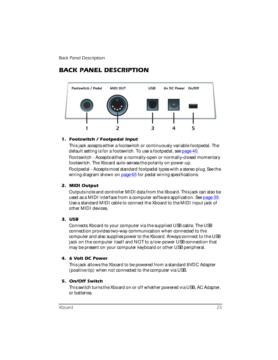
1 | 2 | 3 | 4 | 5 |
1.Footswitch / Footpedal Input
This jack accepts either a footswitch or continuously variable footpedal. The default setting is for a footswitch. To use a footpedal, see page 40.
Footswitch - Accepts either a
Footpedal - Accepts most standard footpedal types with a stereo plug. See the wiring diagram shown on page 65 for pedal wiring specifications.
2.MIDI Output
Outputs note and controller MIDI data from the Xboard. This jack can also be used as a MIDI interface from a computer software application. See page 39. Use a standard MIDI cable to connect the Xboard to the MIDI input jack of other MIDI devices.
3.USB
Connects Xboard to your computer via the supplied USB cable. The USB connection provides
4.6 Volt DC Power
This jack allows the Xboard to be powered from a standard 6VDC Adapter (positive tip) when not connected to the computer via USB.
5.On/Off Switch
This switch turns the Xboard on or off whether powered via USB, AC Adapter, or batteries.
Xboard | 23 |