9left - right, mono output
HPWTM owner’s manual
L/R and mono connectors- rear panel
The HPW Mono output connections are located on the Master rear output panel. The output features a male XLR output connector, along with a 1/4” TRS Insert con- nector. The output is a servo balanced XLR jack.
The TRS Insert jack is wired as Tip=Send, Ring=Return, Sleeve= Audio Ground.This is the
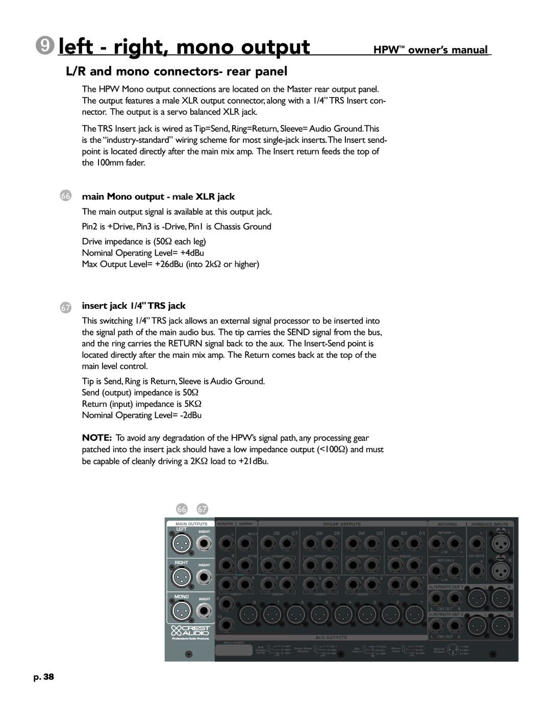
66main Mono output - male XLR jack
The main output signal is available at this output jack. Pin2 is +Drive, Pin3 is
Drive impedance is (50Ω each leg) Nominal Operating Level= +4dBu
Max Output Level= +26dBu (into 2kΩ or higher)
67insert jack 1/4"TRS jack
This switching 1/4” TRS jack allows an external signal processor to be inserted into the signal path of the main audio bus. The tip carries the SEND signal from the bus, and the ring carries the RETURN signal back to the aux. The
Tip is Send, Ring is Return, Sleeve is Audio Ground. Send (output) impedance is 50Ω
Return (input) impedance is 5KΩ Nominal Operating Level=
NOTE: To avoid any degradation of the HPW’s signal path, any processing gear patched into the insert jack should have a low impedance output (<100Ω) and must be capable of cleanly driving a 2KΩ load to +21dBu.
66 67
p.38