Manuals
/
Crown Audio
/
Musical Instruments & Equipment
/
Music Mixer
Crown Audio
IQ-USM 810
service manual
Module Parts
Models:
IQ-USM 810
1
122
172
172
Download
172 pages
16.37 Kb
119
120
121
122
123
124
125
126
Troubleshooting
Specifications
Schematic Diagrams
Clock Signals
Warranty
Maintenance
Reset
Chassis Assembly
Test Procedures
Power Supply
Page 122
Image 122
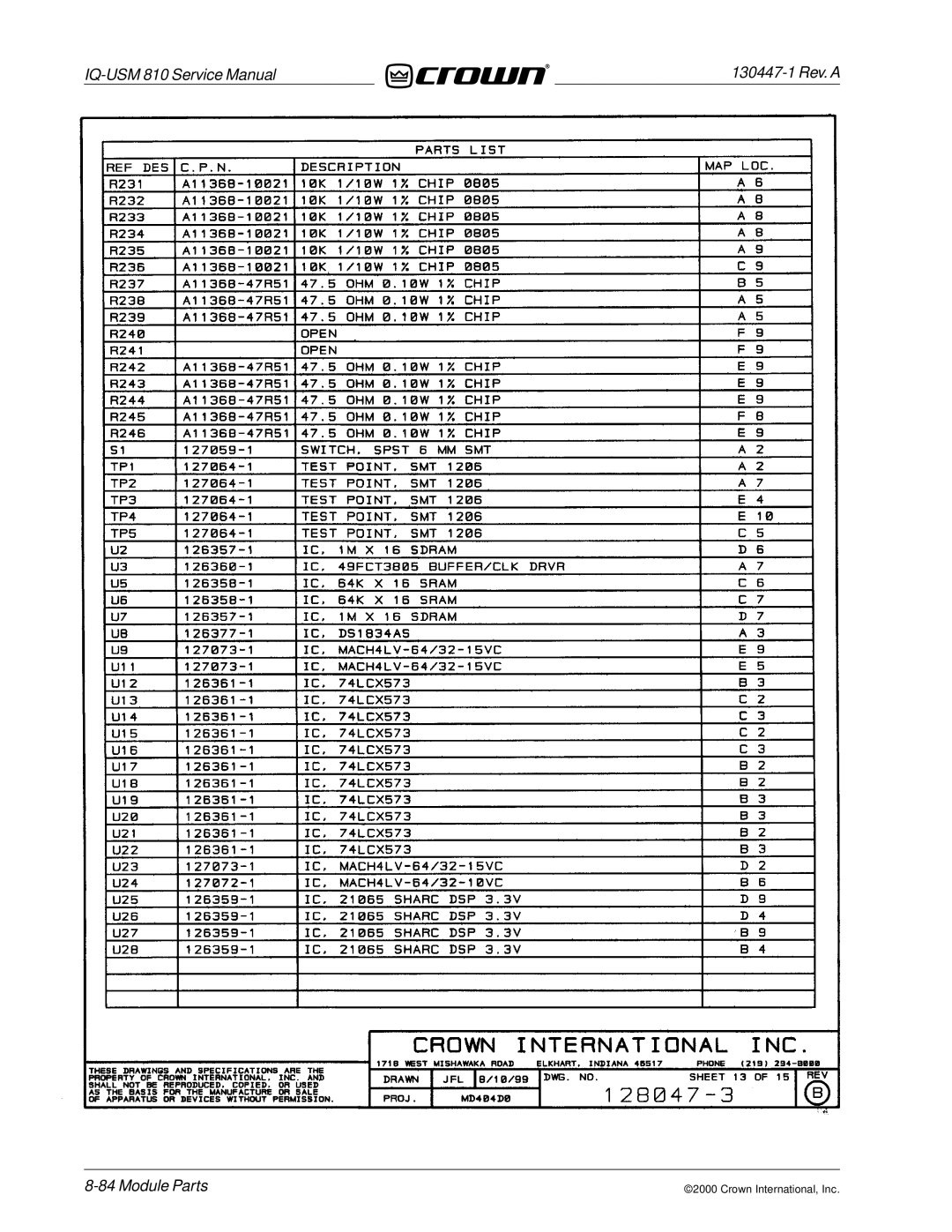
IQ-USM
810 Service Manual
130447-1
Rev. A
8-84
Module Parts
©2000 Crown International, Inc.
Page 121
Page 123
Page 122
Image 122
Page 121
Page 123
Contents
Digital Processor / Digital Mixer
Avis
Revision History
Date
This page intentionally left blank
Table of Contents
Parts Information
Introduction
Warranty
Crown Customer Service
Introduction IQ-USM
IQ-USM 810 Front and Rear Views Introduction
Specifications
Mechanical
This page intentionally left blank
Overview
Power Supply
Circuit Theory
Input
Clock Signals
3 A/D Conversion
Input Analog Processing Circuitry one channel
Output Analog Processing
Output
DC Voltages
Clock Buffers
Sharc Processing
1 +3.3V Power Supply
Reset
Clocks
Bus Utilization
PLDs
Bus Arbitration
DSP Processing
Sharc Pinout
System Controller
Audio Routing
Control Processing
11 68HC12 microcontroller Pinout
Crown Bus Loop
Front Display
2 RS232
Real Time Clock
Definitions
Maintenance
General Information
Required Test Equipment
Standard Initial Conditions
Test Procedures
IQ Message String Syntax
Head Room / Input Clip Level
Control Port Analog Inputs
Display Test
IQ BUS Master Control
HI-POT
Typical Measurements
Test/Debug Objects
Display Test Patterns Maintenance
Display Test Patterns
Error Codes
Troubleshooting FAQs
What is preset P00?
Terms
Parts
Ordering and Receiving Parts
Shipment
This page intentionally left blank
Exploded View Parts
Chassis Assembly Exploded View Parts
Chassis Assembly
Quantity Description CPN
This page intentionally left blank
Schematic Diagrams
IQ-USM 810 Modules
Module and Schematic Information
Module Parts
Module Parts
System Controller Module
PWB #126346-5 Schematic #126451-3 Rev. a
PWA #126451-3
Module Parts
130447-1 Rev. a
Module Parts
130447-1 Rev. a
Module Parts
130447-1 Rev. a
Module Parts
130447-1 Rev. a
PWA #126451-3 Component Map Component Side Module Parts
Input Module
PWB #126689-3 Schematic #126690-3 Rev. a
PWA #126690-3
Module Parts
130447-1 Rev. a
Module Parts
130447-1 Rev. a
Module Parts
130447-1 Rev. a
Module Parts
130447-1 Rev. a
Module Parts
130447-1 Rev. a
Module Parts
130447-1 Rev. a
Module Parts
130447-1 Rev. a
This page intentionally left blank
PWA #126690-3 Component Map Component Side
This Page Intentionally Left Blank
Output Module
PWB #126692-4 Schematic #126693-4 Rev. a
PWA #126693-4
130447-1 Rev. a
130447-1 Rev. a
Module Parts
130447-1 Rev. a
Module Parts
130447-1 Rev. a
Module Parts
130447-1 Rev. a
Module Parts
130447-1 Rev. a
Module Parts
130447-1 Rev. a
This page intentionally left blank
PWA #126693-4 Component Map Component Side
This Page Intentionally Left Blank
Sharc Module
PWB #126743-4 Schematic #126744-3 Rev. a
PWA #126744-3
130447-1 Rev. a
130447-1 Rev. a
Module Parts
130447-1 Rev. a
Module Parts
130447-1 Rev. a
Module Parts
130447-1 Rev. a
Module Parts
130447-1 Rev. a
PWA #126744-3 Component Map Component Side Module Parts
Front Display Module
PWB #126746-3 Schematic #126745 Rev. a
PWA #126747-3
Module Parts
130447-1 Rev. a
This page intentionally left blank
PWA #126747-3 Component Map Component Side
This Page Intentionally Left Blank
PWB #126346-5 Schematic #126323 Rev. a
PWA #128045-1
130447-1 Rev. a
130447-1 Rev. a
Module Parts
130447-1 Rev. a
Module Parts
130447-1 Rev. a
Module Parts
130447-1 Rev. a
PWA #128045-1 Component Map Component Side Module Parts
PWB #126743-4 Schematic #126742 Rev. C
PWA #128047-3
Module Parts
130447-1 Rev. a
Module Parts
130447-1 Rev. a
Module Parts
130447-1 Rev. a
Module Parts
130447-1 Rev. a
Module Parts
130447-1 Rev. a
PWA #128047-3 Component Map Component Side Module Parts
PWB #126743-4 Schematic #126742 Rev. D
PWA #128047-4
Module Parts
130447-1 Rev. a
Module Parts
130447-1 Rev. a
Module Parts
130447-1 Rev. a
Module Parts
130447-1 Rev. a
Module Parts
130447-1 Rev. a
PWA #128047-4 Component Map Component Side Module Parts
PWB #126689-3 Schematic #126688 Rev. a
PWA #128049-1
Module Parts
130447-1 Rev. a
Module Parts
130447-1 Rev. a
Module Parts
130447-1 Rev. a
Module Parts
130447-1 Rev. a
Module Parts
130447-1 Rev. a
Module Parts
130447-1 Rev. a
Module Parts
130447-1 Rev. a
This page intentionally left blank
PWA #128049-1 Component Map Component Side
This Page Intentionally Left Blank
PWB #126692-4 Schematic #126691 Rev. C
PWA #128051-3
130447-1 Rev. a
130447-1 Rev. a
Module Parts
130447-1 Rev. a
Module Parts
130447-1 Rev. a
Module Parts
130447-1 Rev. a
Module Parts
130447-1 Rev. a
Module Parts
130447-1 Rev. a
This page intentionally left blank
PWA #128051-3 Component Map Component Side
This Page Intentionally Left Blank
Schematic Diagrams
This page intentionally left blank
Top
Page
Image
Contents