|
|
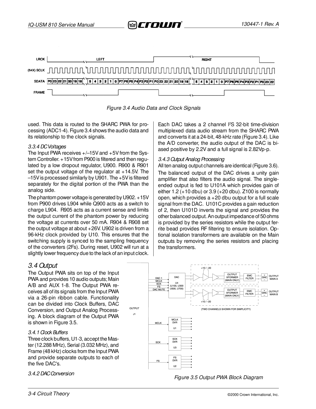
Figure 3.4 Audio Data and Clock Signals
used. This data is routed to the SHARC PWA for pro- cessing
3.3.4 DC Voltages
The Input PWA receives
The phantom power voltage is generated by U902. +15V from P900 drives L904 while Q900 acts as a switch to charge L904. R905 acts as a current sense and limits the output current of the phantom power by reducing the voltage at currents over 50 mA. R904 & R908 set the output voltage at about +26V. U902 is driven from a
Each DAC takes a 2 channel I2S
3.4.3 Output Analog Processing
All ten analog output channels are identical (Figure 3.6).
The balanced output of the DAC drives a unity gain amplifier that also filters the audio signal. The single- ended output is fed to U101A which provides gain of either 1.2 (+10 dbu) or 3.9 (+20 dbu). Z100 is normally open, which provides a +20 dbu output for a full scale signal from the DAC. U101C provides a gain reduction of 2, then U101D inverts the signal and provides the other balanced output. An output impedance of 50 ohms is provided by the series resistors while the output fer- rite bead provides RF filtering to ensure isolation. Op- tional isolation transformers are available on the Main outputs by removing the series resistors and placing the transformers.
3.4 Output
The Output PWA sits on top of the Input PWA and provides 10 audio outputs; Main A/B and AUX
3.4.1 Clock Buffers
Three clock buffers,
3.4.2 DAC Conversion | Figure 3.5 Output PWA Block Diagram |
|
©2000 Crown International, Inc.