|
|
bus and accesses SDRAM when it is available. The SHARC blocks access to the bus through the use of the \SDLOCK pin during SDRAM transfers. SDRAM is utilized only for audio delay processing and has no firm- ware. If audio is available at the input SHARC's, but is not being seen by the output SHARC's, a good place to begin troubleshooting would be with SDRAM.
The System Controller periodically accesses the SHARC's to query about meter data. As discussed, the System Controller utilizes the Interface to ask and re- ceive this data.
3.5.9 Audio Routing
Serial audio from the Input PWA is sent to the SHARC PWA for processing.
The Input Router is also responsible for buffering the audio clocks. By sensing the CNET input from the CNET PWA, the Input Router can tell if the CNET PWA is con-
nected. If CNET is available, the CNET PWA is respon- sible to provide the Serial and Frame Clocks. The PLD accepts the CNET audio clocks and routes them to the SHARC's and Input PWA. If the CNET PWA is not con- nected, the audio clocks from the Input PWA are ac- cepted and routed to the SHARC's.
The Output Router, U11, is responsible for sending the serial audio outputs of the output SHARC's to the ap- propriate place. Five output lines,
3.6 System Controller
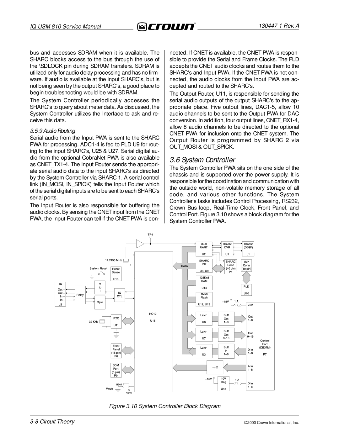
The System Controller PWA sits on the one side of the chassis and is supported over the power supply. It is responsible for the coordination and communication with the outside world,
Figure 3.10 System Controller Block Diagram
3-8 Circuit Theory
©2000 Crown International, Inc.
