CyberPower Network Management System
zDescription
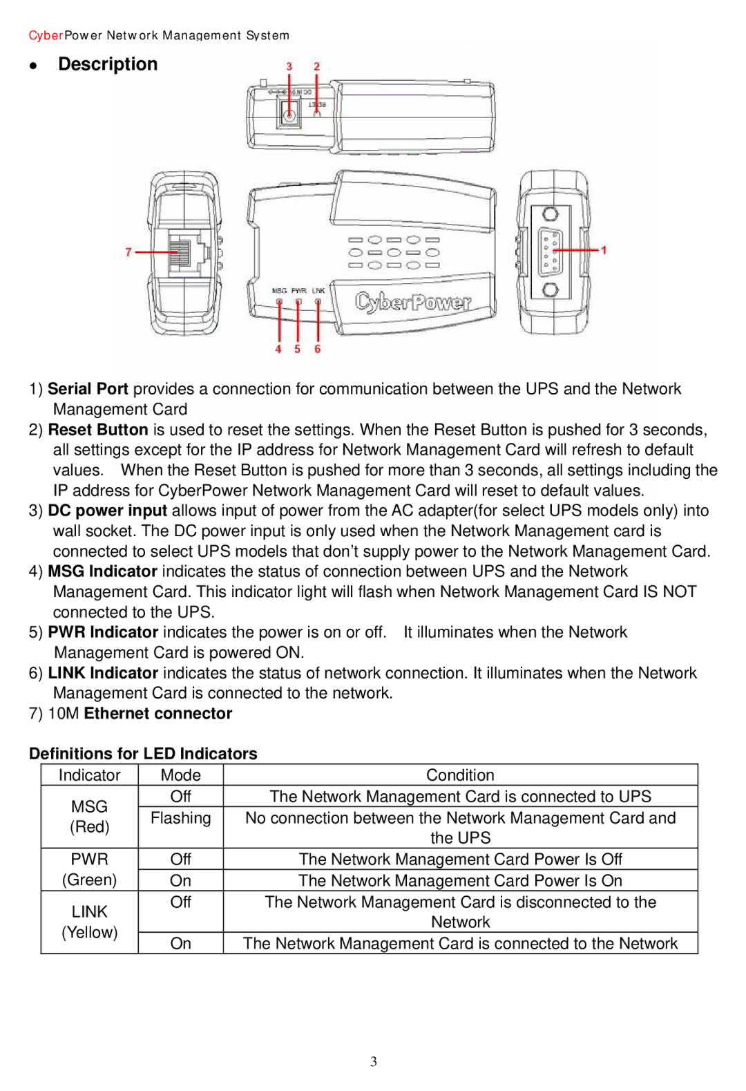
1)Serial Port provides a connection for communication between the UPS and the Network Management Card
2)Reset Button is used to reset the settings. When the Reset Button is pushed for 3 seconds, all settings except for the IP address for Network Management Card will refresh to default values. When the Reset Button is pushed for more than 3 seconds, all settings including the IP address for CyberPower Network Management Card will reset to default values.
3)DC power input allows input of power from the AC adapter(for select UPS models only) into wall socket. The DC power input is only used when the Network Management card is connected to select UPS models that don’t supply power to the Network Management Card.
4)MSG Indicator indicates the status of connection between UPS and the Network Management Card. This indicator light will flash when Network Management Card IS NOT connected to the UPS.
5)PWR Indicator indicates the power is on or off. It illuminates when the Network Management Card is powered ON.
6)LINK Indicator indicates the status of network connection. It illuminates when the Network Management Card is connected to the network.
7)10M Ethernet connector
Definitions for LED Indicators
Indicator | Mode | Condition | |
MSG | Off | The Network Management Card is connected to UPS | |
Flashing | No connection between the Network Management Card and | ||
(Red) | |||
| the UPS | ||
| Off | ||
PWR | The Network Management Card Power Is Off | ||
(Green) | On | The Network Management Card Power Is On | |
LINK | Off | The Network Management Card is disconnected to the | |
| Network | ||
(Yellow) |
| ||
On | The Network Management Card is connected to the Network | ||
|
3