CY7C0837AV, CY7C0830AV

CY7C0831AV, CY7C0832AV

CY7C0832BV, CY7C0833AV

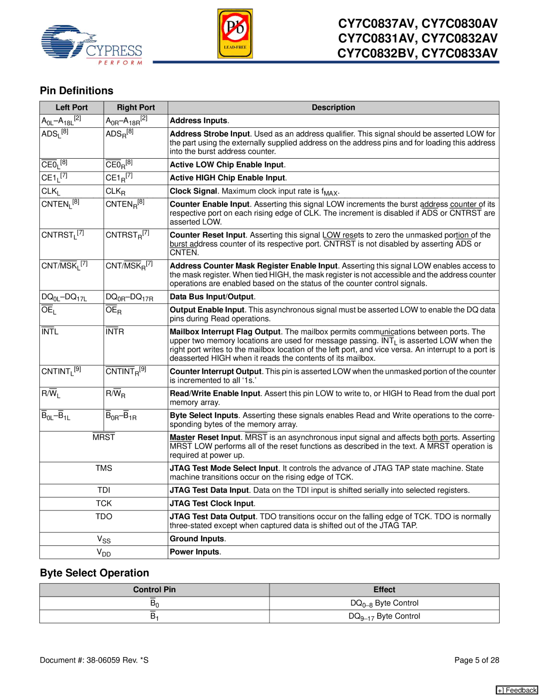
Pin Definitions


Left Port


Right Port


Description


A0L–A18L[2]


A0R–A18R[2]

Address Inputs.


ADSL[8]


ADSR[8]


Address Strobe Input. Used as an address qualifier. This signal should be asserted LOW for


the part using the externally supplied address on the address pins and for loading this address


into the burst address counter.


[8]


[8]


Active LOW Chip Enable Input.


CE0


CE0


L


R


CE1

[7]


CE1

[7]


Active HIGH Chip Enable Input.


L


R


CLKL


CLKR


Clock Signal. Maximum clock input rate is fMAX.


CNTEN

[8]


CNTEN [8]

Counter Enable Input. Asserting this signal LOW increments the burst address counter of its


L


R


respective port on each rising edge of CLK. The increment is disabled if ADS or CNTRST are


asserted LOW.


CNTRST [7]


CNTRST

[7]

Counter Reset Input. Asserting this signal LOW resets to zero the unmasked portion of the


L


R

burst address counter of its respective port. CNTRST is not disabled by asserting ADS or


CNTEN.


L[7]


R[7]

Address Counter Mask Register Enable Input. Asserting this signal LOW enables access to


CNT/MSK


CNT/MSK


the mask register. When tied HIGH, the mask register is not accessible and the address counter


operations are enabled based on the status of the counter control signals.


DQ0L–DQ17L


DQ0R–DQ17R

Data Bus Input/Output.


L


R


Output Enable Input. This asynchronous signal must be asserted LOW to enable the DQ data


OE


OE


pins during Read operations.


Mailbox Interrupt Flag Output. The mailbox permits communications between ports. The


INTL


INTR


upper two memory locations are used for message passing. INTL is asserted LOW when the


right port writes to the mailbox location of the left port, and vice versa. An interrupt to a port is


deasserted HIGH when it reads the contents of its mailbox.


CNTINT

[9]


[9]

Counter Interrupt Output. This pin is asserted LOW when the unmasked portion of the counter


CNTINT


L


R

is incremented to all ‘1s.’


L


R


Read/Write Enable Input. Assert this pin LOW to write to, or HIGH to Read from the dual port


R/W


R/W


memory array.


1L


1R


Byte Select Inputs. Asserting these signals enables Read and Write operations to the corre-


B

0L–B


B

0R–B


sponding bytes of the memory array.


Master Reset Input.


is an asynchronous input signal and affects both ports. Asserting


MRST


MRST


MRST LOW performs all of the reset functions as described in the text. A MRST operation is


required at power up.


TMS


JTAG Test Mode Select Input. It controls the advance of JTAG TAP state machine. State


machine transitions occur on the rising edge of TCK.


TDI


JTAG Test Data Input. Data on the TDI input is shifted serially into selected registers.


TCK


JTAG Test Clock Input.


TDO


JTAG Test Data Output. TDO transitions occur on the falling edge of TCK. TDO is normally


three-stated except when captured data is shifted out of the JTAG TAP.


VSS


Ground Inputs.


VDD


Power Inputs.

Byte Select Operation

Control Pin

Effect


0

DQ0–8Byte Control


B


1

DQ9–17Byte Control


B

Document #: 38-06059 Rev. *S

Page 5 of 28

[+] Feedback

Page 5
Image 5
Cypress CY7C0831AV, CY7C0837AV, CY7C0832BV, CY7C0833AV, CY7C0830AV, CY7C0832AV manual Pin Definitions, Byte Select Operation

CY7C0837AV, CY7C0833AV, CY7C0831AV, CY7C0830AV, CY7C0832AV specifications

Cypress Semiconductor, a leader in innovative semiconductor solutions, has developed a range of high-performance SRAM (Static Random Access Memory) products, including the CY7C0837AV, CY7C0833AV, CY7C0831AV, CY7C0830AV, and CY7C0832AV. These devices cater to various applications requiring fast, reliable memory storage.

One of the main features of these SRAMs is their speed. They offer fast access times, which range from 10 to 15 nanoseconds. This rapid access is critical for applications where speed is essential, such as high-speed networking and telecommunications equipment, automotive systems, and industrial controls. The CY7C0837AV, for instance, boasts a 1 Mbit memory capacity, making it suitable for applications requiring a larger data buffer.

Another notable feature of these devices is their low power consumption. The SRAMs are designed to operate at low voltages, typically around 3.3V, which greatly reduces the overall power requirements. This characteristic is particularly advantageous for battery-operated devices and portable electronics, as it extends battery life and improves energy efficiency.

Cypress's SRAM offerings incorporate advanced technologies like asynchronous read and write operations, which enable users to access memory without the need for a clock signal. This asynchronous nature allows for simpler system designs and integration, significantly reducing component count and complexity.

In terms of packaging, these SRAMs are available in various formats, including standard DIP and surface-mount options, facilitating easy integration into a range of printed circuit boards. Their footprint and compatibility with existing designs ensure they can be utilized in both new developments and legacy system enhancements.

The CY7C0837AV, CY7C0833AV, CY7C0831AV, CY7C0830AV, and CY7C0832AV also support burst mode operations, allowing for faster sequential data access. This feature enhances performance in applications that require continuous data streams, such as video processing and signal processing tasks.

In summary, the Cypress CY7C0837AV, CY7C0833AV, CY7C0831AV, CY7C0830AV, and CY7C0832AV SRAMs provide a combination of high speed, low power consumption, and versatile packaging options. Their advanced technologies and characteristics make them ideal for a wide range of applications, from automotive to industrial systems, solidifying their position as reliable memory solutions in the semiconductor market.