CY7C1370DV25
CY7C1372DV25
2.5V TAP AC Test Conditions
Input pulse levels | VSS to 2.5V |
Input rise and fall time | 1 ns |
Input timing reference levels | 1.25V |
Output reference levels | 1.25V |
Test load termination supply voltage | 1.25V |
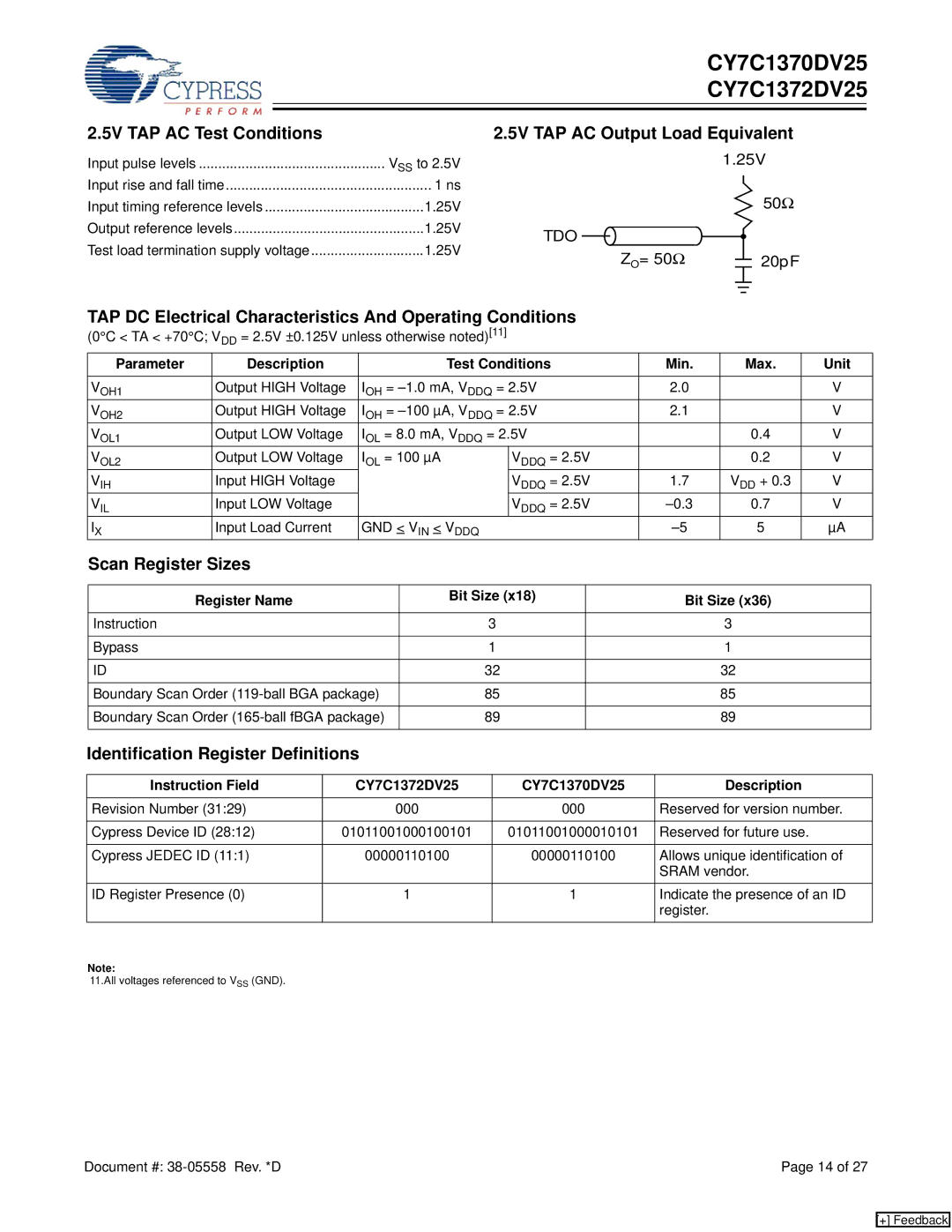
2.5V TAP AC Output Load Equivalent
1.25V
50Ω
TDO ![]()
ZO= 50Ω |
|
|
|
|
|
| 20pF |
|
|
|
|
|
| ||
|
|
|
|
|
|
|
|
|
|
|
|
|
|
|
|
|
|
|
|
|
|
|
|
TAP DC Electrical Characteristics And Operating Conditions |
|
|
| |||||||
(0°C < TA < +70°C; V = 2.5V ±0.125V unless otherwise noted)[11] |
|
|
| |||||||
|
| DD |
|
|
|
|
|
|
|
|
Parameter |
| Description |
|
| Test Conditions | Min. | Max. | Unit | ||
|
|
|
|
|
|
|
|
| ||
VOH1 |
| Output HIGH Voltage | IOH = | 2.0 |
| V | ||||
VOH2 |
| Output HIGH Voltage | IOH = | 2.1 |
| V | ||||
VOL1 |
| Output LOW Voltage | IOL = 8.0 mA, VDDQ = 2.5V |
| 0.4 | V | ||||
VOL2 |
| Output LOW Voltage | IOL = 100 µA |
| VDDQ = 2.5V |
| 0.2 | V | ||
VIH |
| Input HIGH Voltage |
|
|
| VDDQ = 2.5V | 1.7 | VDD + 0.3 | V | |
VIL |
| Input LOW Voltage |
|
|
| VDDQ = 2.5V | 0.7 | V | ||
IX |
| Input Load Current | GND < VIN < VDDQ | 5 | µA | |||||
Scan Register Sizes |
|
|
|
|
|
|
|
| ||
|
|
|
|
|
|
|
| |||
| Register Name |
|
| Bit Size (x18) |
| Bit Size (x36) |
| |||
|
|
|
|
|
|
|
|
|
|
|
Instruction |
|
|
|
| 3 |
|
|
| 3 |
|
|
|
|
|
|
|
|
|
|
|
|
Bypass |
|
|
|
| 1 |
|
|
| 1 |
|
|
|
|
|
|
|
|
|
|
|
|
ID |
|
|
|
| 32 |
|
|
| 32 |
|
|
|
|
|
|
|
|
| |||
Boundary Scan Order |
| 85 |
|
|
| 85 |
| |||
|
|
|
|
|
|
|
| |||
Boundary Scan Order |
| 89 |
|
|
| 89 |
| |||
|
|
|
|
|
|
|
|
|
|
|
Identification Register Definitions
Instruction Field | CY7C1372DV25 | CY7C1370DV25 | Description |
|
|
|
|
Revision Number (31:29) | 000 | 000 | Reserved for version number. |
|
|
|
|
Cypress Device ID (28:12) | 01011001000100101 | 01011001000010101 | Reserved for future use. |
|
|
|
|
Cypress JEDEC ID (11:1) | 00000110100 | 00000110100 | Allows unique identification of |
|
|
| SRAM vendor. |
ID Register Presence (0) | 1 | 1 | Indicate the presence of an ID |
|
|
| register. |
Note: |
|
|
|
11.All voltages referenced to VSS (GND). |
|
|
|
Document #: | Page 14 of 27 |
[+] Feedback