CY7C1470V25

CY7C1472V25

CY7C1474V25

72-Mbit(2M x 36/4M x 18/1M x 72) Pipelined SRAM with NoBL™ Architecture

Features

Pin-compatible and functionally equivalent to ZBT™

Supports 250-MHz bus operations with zero wait states

Available speed grades are 250, 200 and 167 MHz

Internally self-timed output buffer control to eliminate the need to use asynchronous OE

Fully registered (inputs and outputs) for pipelined operation

Byte Write capability

Single 2.5V power supply

2.5V/1.8V I/O supply (VDDQ)

Fast clock-to-output times

3.0 ns (for 250-MHz device)

Clock Enable (CEN) pin to suspend operation

Synchronous self-timed writes

CY7C1470V25, CY7C1472V25 available in JEDEC-standard lead-free 100-pin TQFP, lead-free and non-lead-free 165-ball FBGA package. CY7C1474V25 available in lead-free and non-lead-free 209 ball FBGA package

IEEE 1149.1 JTAG Boundary Scan compatible

Burst capability—linear or interleaved burst order

“ZZ” Sleep Mode option and Stop Clock option

Functional Description

The CY7C1470V25/CY7C1472V25/CY7C1474V25 are 2.5V, 2M x 36/4M x 18/1M x 72 Synchronous pipelined burst SRAMs with No Bus Latency™ (NoBL™) logic, respectively. They are designed to support unlimited true back-to-back Read/Write

operations with no wait states. The CY7C1470V25/CY7C1472V25/CY7C1474V25 are equipped with the advanced (NoBL) logic required to enable consec- utive Read/Write operations with data being transferred on every clock cycle. This feature dramatically improves the throughput of data in systems that require frequent Write/Read transitions. The CY7C1470V25/CY7C1472V25/CY7C1474V25 are pin-compatible and functionally equivalent to ZBT devices.

All synchronous inputs pass through input registers controlled by the rising edge of the clock. All data outputs pass through output registers controlled by the rising edge of the clock. The clock input is qualified by the Clock Enable (CEN) signal, which when deasserted suspends operation and extends the previous clock cycle. Write operations are controlled by the Byte Write Selects (BWa–BWhfor CY7C1474V25, BWa–BWdfor CY7C1470V25 and BWa–BWbfor CY7C1472V25) and a Write Enable (WE) input. All writes are conducted with on-chip synchronous self-timed write circuitry.

Three synchronous Chip Enables (CE1, CE2, CE3) and an asynchronous Output Enable (OE) provide for easy bank selection and output tri-state control. In order to avoid bus contention, the output drivers are synchronously tri-stated during the data portion of a write sequence.

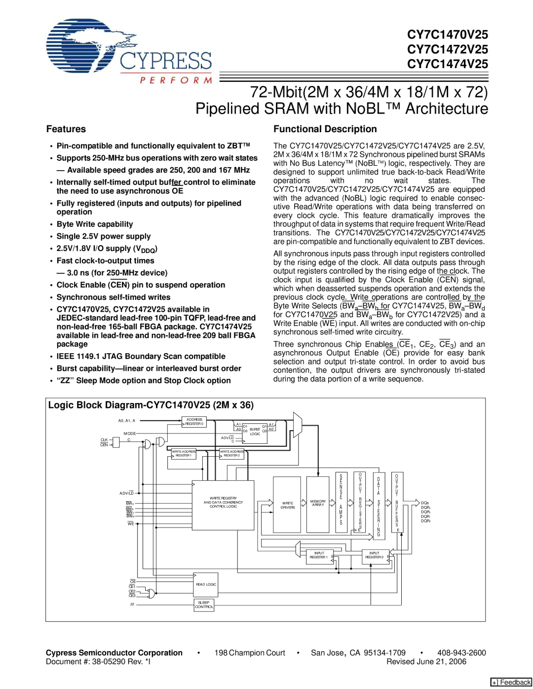
Logic Block Diagram-CY7C1470V25 (2M x 36)


A0, A1, A

ADDRESS


REGISTER 0

A1

D1

Q1

A1'


MODE


A0

D0 BURST Q0 A0'


ADV/LD

LOGIC


CLK

C


C


CEN


WRITE ADDRESS

WRITE ADDRESS


REGISTER 1

REGISTER 2


S

O


O


U

D


E

T

U


P

A

T


N


U

T

P


ADV/LD


S

T

A

U


R

T


WRITE REGISTRY


MEMORY

E

S

B


BWa


AND DATA COHERENCY


WRITE


E


ARRAY


BWb


CONTROL LOGIC


DRIVERS

A

G

T

U


I

F


BWc


M

S

E


F


BWd


P

T

E

E


E


WE


S

R

R

R


S

I

S


E

N

E


G


INPUT

E


INPUT

E


REGISTER 1


REGISTER 0


OE

READ LOGIC


CE1


CE2


CE3


ZZ

SLEEP


CONTROL


DQs DQPa DQPb DQPc DQPd

Cypress Semiconductor Corporation

198 Champion Court • San Jose, CA 95134-1709

408-943-2600

Document #: 38-05290 Rev. *I


Revised June 21, 2006

[+] Feedback

Page 1
Image 1
Cypress CY7C1474V25, CY7C1472V25 manual Features, Functional Description, Logic Block Diagram-CY7C1470V25 2M x

CY7C1474V25, CY7C1470V25, CY7C1472V25 specifications

The Cypress CY7C1470V25, CY7C1474V25, and CY7C1472V25 are part of Cypress Semiconductor’s family of high-performance synchronous static random-access memory (SRAM) solutions. These memory devices are designed specifically for applications that require fast access times and high bandwidth, making them ideal for a variety of consumer and industrial applications.

One of the standout features of these SRAMs is their performance. They provide high-speed access times, with data transfer rates that can reach up to 1 GHz. This performance is particularly beneficial for high-speed applications including networking equipment, telecommunications, and video processing systems. The CY7C1470V25, for example, offers a 256K x 16 configuration with an access time as low as 3.5 ns. Similarly, the CY7C1474V25 and CY7C1472V25 variants provide respective memory sizes of 1M x 16 and 512K x 16, catering to diverse memory application needs.

These SRAMs utilize a synchronous interface, which provides greater control over data transfers and synchronization with external clock signals. This synchronous operation allows for more efficient data handling in high-speed environments, reducing latency and improving system performance overall.

In terms of power consumption, the Cypress CY7C147x series is designed to operate efficiently. With a low operating voltage of 2.5V, these devices minimize energy usage while still delivering high-speed performance. The low standby power makes them suitable for battery-operated devices, as well as for systems where energy efficiency is a priority.

Furthermore, these SRAMs come with built-in features such as burst mode, which allows for sequential data access, enhancing read and write operations. This is especially useful in applications requiring rapid data retrieval.

The packaging options for the CY7C1470V25, CY7C1474V25, and CY7C1472V25 include both fine-pitch ball grid array (FBGA) and other configurations, facilitating easy integration into various circuit board layouts.

In conclusion, the Cypress CY7C1470V25, CY7C1474V25, and CY7C1472V25 SRAMs are powerful memory solutions that combine high-speed performance, low power consumption, and a synchronous interface. Their robust design makes them suitable for a wide array of applications ranging from communications to consumer electronics, ensuring they meet the demands of modern technology.